LED display has become a favorite of outdoor media advertising during these years. Effective maintenance ensures long-term stable operation of outdoor LED displays, so below are ten tips:
1)Switching Sequence
A. Switch on the control computer first, then the liantronics LED display,
B. Switch off the LED display first, then the control computer.
2)Replace the fractured or damaged screws, pins, bearing beams, etc in time especially.
3)Inspect anti-corrosion and anti-rust paint of products and steel structure welding point in regular time. If it occurs the situation of flaking or rusting, engineers should spray anti-rust paint in time.
4)The power supply should be stable and well grounded. Do not switch on the LED display in harsh natural conditions, especially in thunderstorms. Inspect the lightning rod and grounding system in regular time.
5)Check if there is any water leakage in rainy season.
6)Check if there is any damage or bite by animals on the power supply or cables in regular time.
7)Check the power distribution system every half year.
8)LED display which exposes to outdoor environment for a long time is easy to get dirty. Use ethyl alcohol or hairbrush or vacuum cleaner to wipe away the dust, but do not use wet cloth.
9)Test switching on, switching off, brightness adjustment, program list and other functions one by one under automatic default mode.
10) Outdoor LED display needs 2 hours or more turn-off intervals, and it needs to be switched on at least one time per week in the rainy season. Besides, it needs to be used at least one time for at least 2 hours per month.


Multifunctional Applications of Biometric Tablets in Modern Technology


In an era where security and efficiency are paramount, the integration of biometrics into portable devices has revolutionized industries. One such innovation is the biometric tablet, a device that combines advanced biometric scanning capabilities with powerful computing capabilities. This blog explores the uses of biometric tablets, focusing specifically on models with IP68 standards, FBI-certified fingerprint scanners, and a powerful set of specs.

Biometric tablet


Learn about biometric tablets


Biometric fingerprint tablets are specialized devices that utilize biometric authentication methods, such as fingerprint scanning, to enhance security and simplify operations. These tablets are particularly useful in areas where data integrity and user authentication are critical, such as healthcare, finance and law enforcement. The incorporation of biometric technologies not only ensures secure access to sensitive information but also facilitates efficient data management and transaction processing.

biometric fingerprint tablet


Key Features of Biometric Tablets


This biometric tablet is designed to meet the stringent requirements of a variety of professional environments. Compliant with IP68 standard, dustproof and waterproof, suitable for use in harsh conditions. This durability is critical for field work, where exposure to harsh environments can impair the functionality of standard equipment.


The tablet comes with an FBI-certified fingerprint scanner, providing a high level of security. This certification demonstrates that the device meets strict biometric performance standards, ensuring user authentication is reliable and accurate. This feature is particularly beneficial in sectors such as law enforcement, where secure access to sensitive data is critical.


The tablet’s connectivity options are extensive, with 5G network capabilities for fast data transfer and communication. This is critical for professionals who need real-time access to information, such as medical personnel in emergencies or field agents conducting investigations. In addition, the device also includes a rich set of ports such as HDMI, RJ45, RJ232 and Lora, allowing seamless integration with a variety of peripherals and systems.


In terms of performance, the tablet is powered by an octa-core 2.4GHz CPU, ensuring that it can handle demanding applications and multitasking with ease. This processing power is critical for professionals who rely on complex software for data analysis, reporting or real-time monitoring.


Another noteworthy feature is the removable battery with a capacity of up to 10,000mAh. This allows for extended use without the need for frequent charging, making it ideal for professionals who travel frequently or work in remote areas.


 Biometric Tablet Application


The applications for biometric tablets are wide and varied. In healthcare, for example, these devices can be used for patient identification, ensuring medical records are accurately matched to the correct individual. This not only improves patient safety but also streamlines administrative processes.


In the financial sector, biometric tablets can facilitate secure transactions and account access, reducing the risk of fraud. The combination of biometric authentication and high-speed connectivity ensures financial institutions can operate efficiently while maintaining strict security measures.


Law enforcement agencies can utilize biometric tablets for field operations, allowing officers to access databases and verify identities on the spot. This capability can significantly increase the effectiveness of investigations and improve public safety.


In summary, biometric tablets represent a significant advancement in portable technology, offering a combination of security, performance and versatility. With features such as IP68 protection, biometric police tablet, and powerful processing capabilities, these devices are ideal for a variety of professional applications. As the industry continues to evolve and prioritize security and efficiency, biometric tablet adoption is likely to increase, paving the way for a more secure and streamlined future.


4G Biometric tablet

By any metric, the New York Marathon is an immense production. The 50,000+ runners who make this the world's largest marathon. Their route will take them through all five of the city's boroughs, from the starting line on Staten Island up through Brooklyn and Queens, across the Queensboro Bridge to Manhattan's Upper East Side, north into the Bronx and then back down along the east side of Central Park to the finish line in the Park itself.


ham radio walkie talkie commercial 2 way radio


Ensuring that the whole thing goes off without a hitch is a remarkable feat of organization. The race relies on a small army of volunteers, who do everything from staffing the water stations at every mile marker and making sure runners don't get lost to offering medical expertise.


Perhaps more than anything else, though, coordinating an event with so many moving pieces requires reliable, efficient communications. Volunteers play a critical role here, too, including one very specific group: local amateur radio (or "ham radio walkie talkie") operators.

Donni Katzovicz is a ham radio enthusiast who has volunteered at the Marathon since 2018 through Event Hams, a group that has coordinated the Marathon's use of amateur radio for the last decade. He explains that ham radio essentially plays two key roles during the marathon.


commercial 2 way radio handheld walkie talkies


The first is as a route for communications that don’t require the use of official channels. “Obviously,” he says, “The marathon has commercial 2 way radio licenses and its own communications infrastructure. You also have all the local emergency services—FDNY, NYPD, EMS. And they all have their own radios and equipment.”


As well as chasing down people with overly extravagant costumes, however, ham radio also stands ready to play a second, more critical role: providing a reliable and resilient backup method of communications if primary channels go down for whatever reason. Katzovicz says, “If there was a major failure of all the major, super-critical systems, organizers know that there’s still a backup there.”

At the most basic level, ham radio is any radio that operates on the radio bands reserved for amateurs. As Katzovicz explains, enthusiasts come up with all manner of uses for their little corner of the electromagnetic spectrum: “The hobby itself is really, really, incredibly broad and encompasses a lot of different parts of science and technology. Some people … have handheld walkie talkies and to talk to other licensed people in their neighborhood; others make their own radios or make their own Rube Goldberg-esque devices to listen and transmit, and others coordinate with local civil bodies and provide backup communications.”


handheld walkie talkies ham radio walkie talkie


In a scenario where, say, all a city’s power was out, battery-powered walkie talkies would still work just fine, whereas cell phones would be useless.


All being well, the ham enthusiasts volunteering during this year's Marathon won't be required to do anything more taxing than chase down oversized donuts. But if for whatever reason their emergency backup services are required, the city's ham enthusiasts are on hand to ensure that the show can go on.

Ham radio enthusiasts from throughout the region were at the Polk County Fairgrounds on Saturday, drawn by the lure of the semi-annual swap meet.


VHF UHF radio


For some, ham radio is a hobby. Hams tends to use two kinds of gear: HF and VHF/UHF. HF gear is made to talk over long distances, while VHF/UHF radio is for talking around town. But for Kjell Lindgren, it was an out-of-this-world experience.


Lindgren is an American astronaut. One mission took him to the International Space Station (ISS). While orbiting, he called ham radio operators in the United States.

This call came on the ARRL Radio National Field Day. The annual event is “for amateur radio operators to practice emergency preparedness and radio communications,” according to published reports.

“I was eight years old. I had a shortwave radio, and was listening to shortwave broadcasts from around the world,” Rosenfeld said. “I was amazed that these sig nals could somehow end up in my bedroom.”

For many, a ham radio is an essential part of an emergency preparedness tool box. This importance has been on display along the East Coast, where hurricanes Helene and Milton have wreaked considerable damage.

Ham radios work when other forms of communication don't. "(That's) huge, especially with the first one (Helene) that went through North Carolina. You could listen on the radio. They were able to facilitate getting aid to a lot of people,” said Josh Scott, Yamhill County Amateur Radio Emergency Services Group. “And in those events, there were people getting on their radio that weren't licensed. But they were still able to get on the Frs two way radio and ask for help.”


 Frs two way radio


Oregon isn't home to major hurricanes. But local residents have their own worries. Fires, for example, and a ticking time bomb off the coast.


“If the Cascadia earthquake were to hit, the reality is that we will probably not have cell phones or telephones of any sort. The Internet will be down,”Scott said. "The only way you're going to be able to communicate after Cascadia is with radios.”


Ham radio


“Ham radios used to be more popular. Most of the people in their 70s and 80s were part of ham radio clubs and got their licenses. This was in almost every school,” she said. “Now, there’s a lot less of that going on. It’s a great hobby. But it’s going to be very valuable when the big one hits.”

The environment of an electron microscopy lab does not directly impact the electron microscope itself but rather affects the imaging quality and overall performance of the microscope. During the operation of an electron microscope, the fine electron beam needs to travel in a high vacuum environment, covering a distance of 0.7 meters (for Scanning Electron Microscope) to over 2 meters (for Transmission Electron Microscope). Along the path, external factors such as magnetic fields, ground vibrations, noise in the air, and airflows can cause the electron beam to deviate from its intended path, leading to a degradation in imaging quality. Therefore, specific requirements need to be met for the surrounding environment.


As is well known, electromagnetic waves consist of alternating magnetic and electric fields. However, it is important to consider the frequency when measuring electromagnetic waves using either magnetic or electric fields. In practice, it is necessary to take the frequency into account.


At very low frequencies (as the frequency tends to zero, equivalent to a DC magnetic field), the magnetic component of the electromagnetic wave becomes stronger while the electric component weakens. As the frequency increases, the electric component strengthens and the magnetic component decreases. This is a gradual transition without a distinct turning point. Generally, from zero to a few kilohertz, the magnetic field component can be well characterized, and units such as Gauss or Tesla are used to measure the field strength. Above 100 kHz, the electric field component is better measured, and the unit used for field strength is volts per meter (V/m). When dealing with a low-frequency electromagnetic environment with a strong magnetic field component, reducing the magnetic field directly is an effective approach.


Next, we will focus on the practical application of shielding a low-frequency (0-300 Hz), electromagnetic field with a magnetic field strength ranging from 0.5 to 50 milligauss (peak-to-peak) in a shielded volume of 40-120 cubic meters. Considering cost-effectiveness, the shielding material used is typically low-carbon steel plate Q195 (formerly known as A3).


Since the eddy current loss of a single thick material is greater than that of multiple thin layers (with the same total thickness), thicker single-layer materials are preferred unless there are specific requirements. Let's establish a mathematical model:


1. Derivation of the formula

Since the energy of low-frequency electromagnetic waves is mainly composed of magnetic field energy, we can use high-permeability materials to provide magnetic bypass paths to reduce the magnetic flux density inside the shielding volume. By applying the analysis method of parallel shunt circuits, we can derive the calculation formula for the parallel shunting of magnetic flux paths.

Here are some definitions:

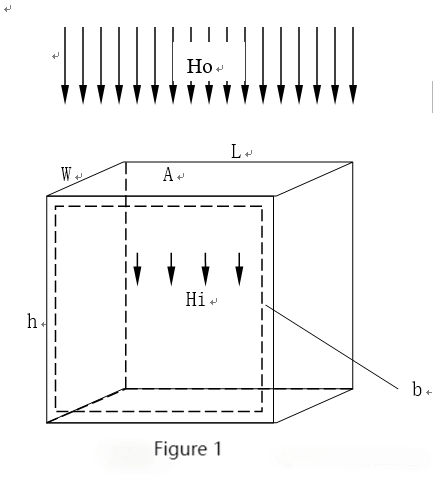
Ho: External magnetic field strength

Hi: Magnetic field strength inside the shielding volume

Hs: Magnetic field strength inside the shielding material

A: Area through which magnetic lines pass through the shield A = L × W

Φo: Permeability of air

Φs: Permeability of the shielding material

Ro: Magnetic resistance of the internal space of the shield

Rs: Magnetic resistance of the shielding material

L: Length of the shielding volume

W: Width of the shielding volume

h: Height of the shielding volume (i.e., length of the magnetic channel)

b: Thickness of the shielding material


From the schematic diagram (Figure 1), we can obtain the following equations:

Ro = h / (A × Φo) = h / (L × W × Φo) (1)

Rs = h / ((2b × W) + (2b × L)) × Φs (2)


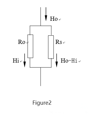
From the equivalent circuit diagram (Figure 2), we can obtain the following equation:

Rs = Hi × Ro / (Ho - Hi) (3)


By substituting equations (1) and (2) into equation (3) and rearranging, we get the formula (4) for calculating the thickness b of the shielding material:

b = L × W × Φo × (Ho - Hi) / ((W + L) × 2Φs × Hi) (4)


Note:

In equation (4), the length of the magnetic channel h is eliminated during the simplification process, and physical units such as Φo, Φs, Ho, Hi, and others are also eliminated. It is only necessary to ensure that the length units are consistent.


From equation (4), it can be seen that the shielding effectiveness is related to the permeability and thickness of the shielding material, as well as the size of the shielding volume. A higher permeability and thicker shielding material result in lower magnetic resistance and higher eddy current losses, leading to better shielding effectiveness. When the permeability and thickness are the same, a larger shielding volume will result in poorer shielding performance.


2. Validation of the formula


We can use equation (4) Φo=1, L=5m, W=4m, Φs=4000 to calculate the thickness of the shielding material and compare the calculated results with experimental data (which took several months to collect):


Table 1


Thickness (mm)

Field Strength (%)

1.5

2

3

4

5

6

8

External magnetic field strength

100

100

100

100

100

100

100

Measured internal magnetic field strength

60~65

45~50

~35

~27

~22

~16

8~12

Calculated internal magnetic field strength

18.5

13.9

9.26

6.94

5.56

4.63

3.47


Note:

1. The external magnetic field strength is in the range of 5-20 milligauss (peak-to-peak).

2. The measured values are obtained by converting multiple tests under different conditions. Since the test conditions for each measurement are not the same, the presented values represent approximate average measurements.


In reality, due to various factors, it is quite challenging to establish a simple mathematical model for analyzing and calculating low-frequency electromagnetic shielding effectiveness. The significant deviations between the calculated results and experimental data can be attributed to the following reasons.


Firstly, the function relationship in the parallel shunt circuit is linear, while in magnetic circuits, permeability, magnetic flux density, and eddy current losses do not exhibit linear relationships. Many parameters are nonlinear functions of each other (although they may exhibit good linearity in certain ranges). During the derivation of the parallel shunting mechanism in magnetic circuits, some parameters were omitted, approximations were made, and conditions were simplified to avoid complex calculations, linearizing the magnetic circuit. These factors are the main reasons for the differences in precision between calculations and experiments.


Secondly, commercial low-carbon steel plate specifications are usually 1.22m × 2.44m in size. Considering a room size of 5m × 4m × 3m as an example, even with full welding, there would still be over 50 welds, and the thickness of the welds is often smaller than that of the steel plate. Additionally, there may be openings and gaps in the shielding material, resulting in an overall increase in magnetic resistance and a decrease in permeability. Therefore, the calculation formula for magnetic shielding derived from the parallel shunt circuit needs to be modified to approach actual conditions.


3. Modified calculation formula

Based on equation (4), we introduce a correction coefficient μ and consider the permeability of air to be approximately 1. The modified equation for calculating the thickness b of the shielding material is as follows (equation 5):

b = μ × [L × W × (Ho - Hi) / ((W + L) × 2Φs × Hi)] (5)


The value of μ is selected between 3.2 and 4.0. A smaller value is preferred for smaller shielding volumes and higher process levels, while a larger value is better for larger shielding volumes. Using equation (5) with μ = 3.4, the calculated results are compared with experimental data (see Table 2), showing significantly improved agreement.


Table 2

Thickness (mm)

Field Strength (%)

1.5

2

3

4

5

6

8

External magnetic field strength

100

100

100

100

100

100

100

Measured internal magnetic field strength

60~65

45~50

~35

~27

~22

~16

8~12

Calculated internal magnetic field strength

62.9

47.2

31.5

23.6

18.9

15.7

11.8


Note: Other conditions remain the same as in Table 1.


It should be noted that multiple test data confirm the high concurrence between the results obtained from equation (5) and various on-site measurements. However, there have been isolated cases with significant deviations. These cases can be attributed to construction issues.


The following are several situations that may occur during construction: 

1. Thin steel plates used in individual areas (such as doors).

2. Non-continuous welding or large gaps in welded joints.

3. Insufficient depth of welds, resulting in decreased permeability at weld locations and multiple "bottlenecks."

4. Larger openings in shielded areas and improper treatment of waveguide openings.

5. Arbitrary shortening of waveguide length or substandard processing.

6. Insufficient wall thickness of waveguide.

7. Multiple grounding points in the shielding material lead to non-uniform current distribution.

8. Connection of the shielding material to the neutral wire of the power supply.


Even a small oversight can lead to a significant deterioration in effectiveness, the capacity of a bucket depends on the shortest piece of wood. For concealed projects like this, quality is often ensured by the craftsmanship. Therefore, it is important to pay careful attention to selecting a reliable construction company, strictly adhering to the design requirements and process, strengthening on-site construction supervision, and implementing phased inspections.


Shielding enclosure aperture design:

When designing a shielding enclosure, one will inevitably encounter the issue of apertures. The theoretical methods commonly used for aperture design are difficult to directly apply to low-frequency magnetic shielding design. Here, we will discuss the example of a room's shielding design.


1. Small apertures: In rooms with small shielded devices, there are usually power supply, energy supply, and cooling water requirements. These auxiliary facilities are mostly located outside the shielding enclosure and are connected through water pipes, air pipes, and cables. These pipes and cables can be appropriately centralized and passed through the shielding enclosure using one or several small holes. These holes, made of the same material as the shielding enclosure, are called "waveguide openings." The length-to-diameter ratio of the waveguide openings is generally considered to be at least 3-4:1 (if the on-site conditions permit, longer is better). For example, if the diameter of a small hole is 80mm, the length should be at least 240-320mm.


2. Medium-sized apertures: Ventilation openings for air conditioning and exhaust openings for fans typically have diameters (or side lengths for squares or rectangles) of around 400-600mm. Calculating the length of a waveguide opening based on these dimensions would result in lengths of 1200-2400mm, which is not feasible in practical construction. In this case, the original aperture can be divided into several smaller openings of the same size using a grid. For example, if a 400×400mm air inlet is divided into nine equal-sized grids, the length would be reduced from 1200-1600mm to 400-530mm (the increase in airflow resistance due to the grids is negligible).


When designing and fabricating, pay attention to the following points:

- The material of the grids should be the same as the shielding enclosure, and the thickness of the material should not be arbitrarily reduced.

- The cross-section of the grids should be as close to square as possible.

- Try to reduce the number of grids as much as possible, within acceptable lengths, to reduce processing difficulties and airflow resistance.

- Ensure continuous welding at all locations of the grids to prevent an increase in magnetic resistance.

- Increase the magnetic permeability by adding silicon steel plates at the junctions of the grids.


3. Large closable apertures: Doors and windows of a room typically have openings measuring 1m×2m or even larger. In this case, the waveguide openings should be designed based on the non-magnetic gaps when the doors and windows are closed (made of the same material as the shielding enclosure). Assuming a non-magnetic gap of 5mm (which is not technically challenging, and additional edge folds can be added in difficult-to-handle areas), the length of the waveguide opening should be 15-20mm. Given that the gap is narrow and long, it is preferable to have a longer length. Note that the waveguide openings are not only formed by the frames of doors and windows; there should be a certain thickness of edge folds at all non-magnetic gap locations to ensure the length of the waveguide opening. To ensure safe evacuation in special circumstances, the door frames of the shielding room should be reinforced, and the shielding doors should open outward.


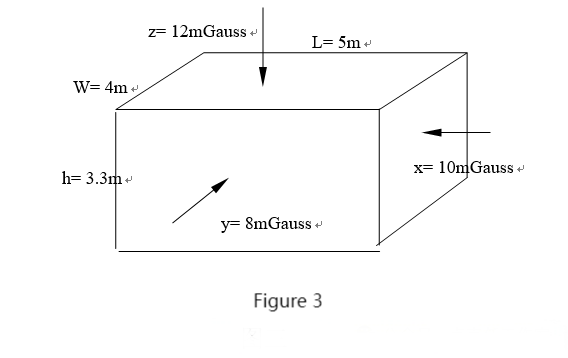
Here is a practical design example:

The dimensions of the room are length 5m, width 4m, and height 3.3m, with original magnetic field strengths of x=10mGauss, y=8mGauss, and z=12mGauss. The goal is to design a low-frequency electromagnetic shielding that ensures the magnetic field strength in any direction inside the enclosure is less than 2mGauss. See Figure 3.


1. Select commercial low-carbon steel plates with Φs=4000 and specifications of 1.22m×2.44m.

2. Use equation (5) to calculate the thickness of the steel plates from the x, y, and z directions:

Taking μ as 3.8, substitute the given length, width, and height into L×W, corresponding to the original magnetic field strengths in the x, y, and z directions.

bx=3.8〔3.3m×4m×(10mGauss -2mGauss)/(4m+3.3m) 2×4000×2mGauss〕

=3.43mm

by=3.8〔3.3m×5m×(8mGauss -2mGauss)/(5m+3.3m) 2×4000×2mGauss〕

=2.83mm

bz=3.8〔5m×4m×(12mGauss -2mGauss)/(4m+5m) 2×4000×2mGauss〕

=5.28mm   (If lengths and widths are 10m and 6m, respectively, the calculated thickness would be b=2280/56000=8.91mm)

The thickness of all steel plates should be at least 6mm (to allow for environmental magnetic field variations, 8-10mm can be used as well) as a single layer.

All welding seams should be continuous and try to achieve a depth close to the thickness of the base material.


3. Waveguide opening treatment

(Omitted. See the section on shielding enclosure aperture design).

After completion, the shielding enclosure was tested and fully met the design requirements.


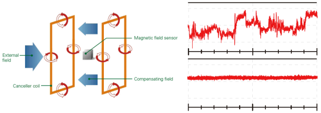
Note: Magnetic shielding cannot improve DC interference environments. When there is a need to improve DC electromagnetic interference environments, it should be used in conjunction with demagnetizers that have DC elimination capabilities.

Do police have portable fingerprint scanners?


Yes, portable fingerprint scanners are used by law enforcement agencies in many countries. These devices allow the police to quickly capture and analyze fingerprints in the field without the need to transport the individuals to a police station or a dedicated fingerprinting facility. Portable fingerprint scanners are compact, lightweight devices that can scan and analyze fingerprints using optical or capacitive technology.

Police portable fingerprint scanner

These scanners typically work by capturing an image of the ridges and valleys on a person's fingertip and converting it into a digital format. The image is then compared against a database of known fingerprints to identify if there is a match. Portable fingerprint scanners are beneficial for on-site identification and verification purposes, aiding in crime scene investigations, suspect identification, and rapid checks of individuals' identities during field operations.

In an era of rapid technological advancement, law enforcement agencies are increasingly turning to innovative tools to improve operational efficiency. One such advancement is the use of portable fingerprint biometric scanners. But do police have portable fingerprint scanners? The answer is yes, and the SFT Portable Android Fingerprint Scanner leads the way.

Android pos fingerprint scanner

The SFT Biometric Fingerprint POS is not an ordinary fingerprint scanner; It is EMV/PCI certified and FBI certified, ensuring it meets the highest standards of security and reliability. This portable device allows officers to quickly and accurately identify people on scene, making it a valuable tool for law enforcement. With its built-in fast receipt printer, officers can provide immediate documentation of investigation results, which is critical to maintaining accurate records during an investigation.

Portable android biometric pos

In addition, SFT scanners are equipped with GPS capabilities, allowing officers to record the exact location of their interactions. This feature is particularly useful for tracking crime patterns and ensuring accountability of police actions. The device also supports 4G network connectivity and can transmit data to a central database in real time. This means officers can obtain vital information about a suspect or missing person without having to return to the police station, significantly speeding up the investigation process.


As crime rates fluctuate and the need for rapid identification grows, it becomes increasingly important to integrate portable fingerprint scanners such as the SFT model into police work. Not only do these devices increase law enforcement efficiency, they also improve public safety by responding to incidents faster.


The answer to whether police have portable fingerprint scanners is clear. With advanced technologies like the SFT Portable Android Fingerprint Scanner, law enforcement agencies can better serve and protect their communities. The future of policing is here, and it's portable.


When choosing a supplier for motorcycle batteries, there are several factors to consider to ensure you make the right choice. Here are some guidelines:


YEEU Motorcycle Battery


Reputation and Experience

Look for a supplier with a solid reputation and a proven track record of providing high-quality motorcycle batteries. Check online reviews, customer testimonials, and ratings to gauge their reliability and customer satisfaction. An experienced supplier will likely have a better understanding of the industry and be able to offer reliable products.


Quality of Batteries

The quality of the batteries offered by the supplier is crucial. Look for suppliers who provide two-wheeler batteries from reputable manufacturers known for their reliability, performance, and durability. Ensure that the batteries meet or exceed industry standards and have the necessary certifications.


Compatibility

Motorcycle batteries come in various types, sizes, and specifications. Choose a supplier that offers a wide range of options to ensure they have batteries compatible with your motorcycle's make, model, and requirements. They should be able to provide batteries with the correct voltage, capacity, and dimensions.


Warranty and Support

A good supplier will provide a warranty on their batteries, indicating their confidence in the product's quality. Check the warranty terms and conditions, including the duration and coverage. Additionally, inquire about their customer support services in case you encounter any issues or require assistance with your battery.


Pricing and Value

Compare prices from different suppliers, but keep in mind that the cheapest option may not always be the best. Consider the overall value offered by the supplier, including the quality of the batteries, warranty terms, customer support, and any additional services they provide.


Distribution and Availability

Ensure that the supplier has a reliable distribution network and sufficient stock availability. You don't want to face delays or difficulties in sourcing batteries when you need them.


Additional Services

Consider whether the supplier offers any value-added services, such as battery testing, installation support, or recycling programs. These services can enhance the overall customer experience.


Recommendations and Referrals

Seek recommendations from fellow motorcycle enthusiasts, mechanics, or industry professionals who have experience with motorcycle batteries. They may be able to provide insights or refer you to reliable suppliers.


By carefully considering these factors, you can choose a reputable and reliable supplier for your motorcycle batteries, ensuring a quality product and a positive experience.

Sealed lead-acid battery is a common type of battery used in portable power stations. This blog is about lead-acid batteries for portable power stations:


Battery For Portable Power Station


Technology

Lead-acid batteries use a chemical reaction between lead plates and sulfuric acid to store and deliver electrical energy. They have been widely used for many years and are known for their reliability and cost-effectiveness.


Voltage and Capacity

Lead-acid batteries used in portable power stations typically have a nominal voltage of 12 volts (12V), similar to car batteries. The capacity of lead-acid batteries can vary and is typically measured in ampere-hours (Ah). Portable power stations may use lead-acid batteries with capacities ranging from a few ampere-hours to several hundred ampere-hours, depending on the application and power requirements. Models that stand out are: 6V4.5Ah, 6V7Ah, 12V4.5Ah, 12V7AH, 12V9Ah, 12V12Ah, etc.


Performance

Lead-acid batteries offer moderate energy density, meaning they can provide a decent amount of power but have a comparatively lower energy-to-weight ratio. They are capable of delivering high current bursts, making them suitable for applications that require high power output, such as providing electricity to power tools, small appliances, or electronic devices during outdoor activities or power outages.


Maintenance

Lead-acid batteries require regular maintenance to ensure their optimal performance and longevity. This includes periodically checking the battery's electrolyte levels, ensuring proper ventilation, and preventing overcharging or deep discharge, which can affect battery life.


Charging

Lead-acid batteries need to be properly charged to maintain their capacity and performance. Portable power stations equipped with lead-acid batteries often include built-in charging systems, which allow the battery to be charged from various power sources, such as AC wall outlets, solar panels, or car adapters.


Weight and Portability

Lead-acid batteries are relatively heavy compared to other battery technologies, such as lithium-ion. This can impact the overall weight and portability of the portable power station. However, advancements in battery design and lightweight materials have allowed for more compact and portable lead-acid battery-based power stations.


However, it's worth noting that while lead-acid batteries offer certain advantages, they also have limitations such as lower energy density and shorter lifespan compared to some other battery technologies. Depending on your specific needs and requirements, you may also consider exploring portable power stations with alternative battery technologies like lithium-ion battery, which offer higher energy density, lighter weight, and longer life.


Portable Power Lead Acid Battery


LED Display, we could simply recognize it as a big size monitor, which is always widely used for commercial applications. It also be named as led screen, led video wall, led display panel, led display billboard etc.,


Light emitting diode, driving ICs and other electronic components  mounted together on current PCB board forms LED display modules; LED modules, switching power supplies and control cards fixed on specialized metal  cabinet forms led display cabinet; several led display cabinets fixed on specialized metal structure and worked with specialized control system; this is the whole led display system.


As it is said, led display is always widely used for commercial application. Main applications would be stage rental, VP virtual production, XR virtual photo shoot, exhibition, creative shape display, advertisement & media, security monitoring, commanding & controlling, transports, meeting room, education, stadium, broadcasting, smart city creation, finance, communication , estate, medical, meteorology, military etc., Advertisement, information display, specific places decoration, and stage background are main usage for led display application. The most common applications we will see would be led displays on the wall of buildings, led displays of cinema stage back ground, led display on evet stage, and led displays in night club...


LED Display for XR virtual shooting

LED display screens are classified into different categories based on various criteria. Initially, there were several classification methods, which included:
1. Installation Scene: Indoor LED display screens and outdoor LED display screens.
2. LED Encapsulation Type: DIP LED display screens, SMD LED display screens, and dot matrix LED display screens.
3. Display Color: Single color LED display screens, dual color LED display screens, and full-color LED display screens.
4. Pixel Pitch: This classification refers to the commonly heard "P" number for LED display screens. Popular pixel pitch of display screens now ranges from less than 1 millimeters to 10 millimeters.

With the continuous advancement of LED display screen technology and its increasing application scenarios, the classification of LED display screens has become more detailed. One notable example is rental LED display screens. In the beginning, rental LED display screens were primarily achieved by reducing the weight of indoor and outdoor screen bodies and equipping them with corresponding fast locks, without significant changes in appearance and size. However, as the technology of various components in the LED display screen supply chain has improved, the current rental cabinets can achieve both aesthetic appeal and lightweight design, truly meeting the requirements of quick assembly, disassembly, and easy transportation.

Currently, the most popular LED display screens in the market include small pixel pitch LED display screens, GOB LED display screens, COB LED display screens, and creative LED display screens. These advancements have revolutionized the visual experience and expanded the possibilities of LED display screens.

Choose the right LED display screen for your needs and elevate the impact of your presentations, advertisements, and visual displays. Experience the impressive capabilities of LED display screens and unlock a world of vibrant and dynamic visuals.