FTTH network:PON vs AON
Fiber to the Home (FTTH) is a communication technology that involves the transmission of signals directly to users' homes via optical fibers. Compared to traditional copper cable connections, FTTH offers higher bandwidth, faster transmission speeds, and longer transmission distances. In recent years, due to the rapid growth of internet applications and the increasing demand for high-speed broadband, FTTH has emerged as the mainstream choice for broadband access.
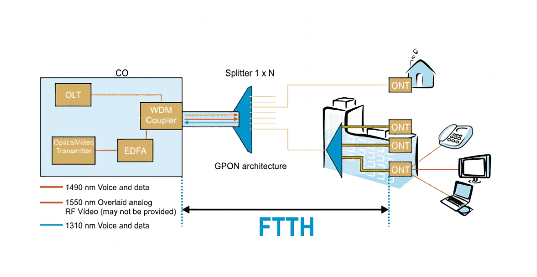
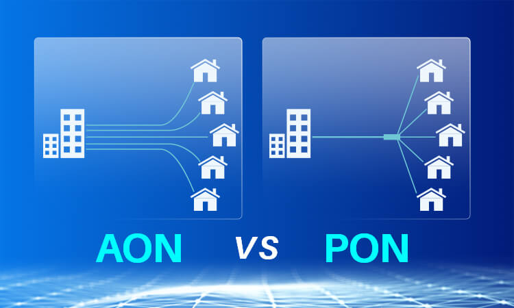
FTTH networks primarily utilize two types of architectures: Passive Optical Network (PON) and Active Optical Network (AON). PON systems rely on passive splitters to distribute optical signals without the need for powered equipment, while AON systems utilize active devices such as switches and routers to amplify and distribute the signals.
Main Implementation Methods of FTTH Networks: PON and AON
FTTH networks primarily utilize two implementation methods: Passive Optical Network (PON) and Active Optical Network (AON). These two technologies differ significantly in network architecture, key components, and application scenarios.
Passive Optical Networks (PON)
Passive Optical Network (PON) is a type of fiber optic network that operates without the need for active intermediary devices such as amplifiers or switches.
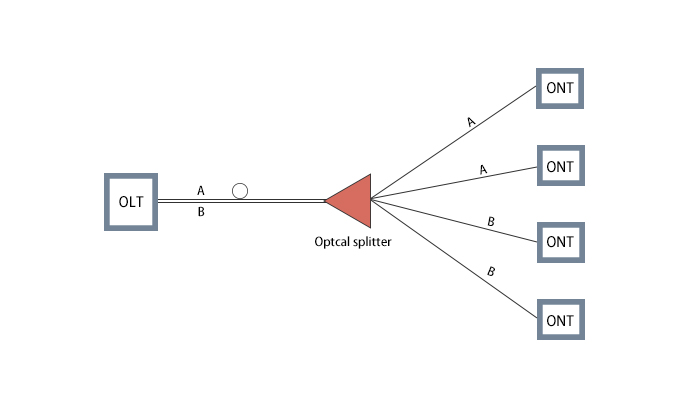
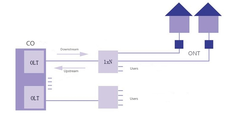
In PON system, the Optical Line Terminal (OLT) is situated at the service provider's end and connects through fiber optics to multiple Optical Network Units (ONU) or Optical Network Terminals (ONT). The distribution of optical signals between these components is managed by passive splitters. PON systems are known for their low cost and simple maintenance, making them widely used in FTTH networks.
Active Optical Network (AON)
Active Optical Network (AON) relies on active intermediary devices such as switches and routers to amplify and distribute optical signals.
In AON system, each user has an individual fiber connection to a central switch or router, allowing for higher bandwidth and more flexible quality of service management. Although the initial setup costs for AON system are higher and maintenance is more complex, its performance and service quality advantages make it competitive for high-end applications.
Passive Optical Networks (PON)
Passive Optical Network (PON) is a fiber-optic access network that operates without the need for any active intermediary devices, such as amplifiers or switches. The core component of a PON system is the passive splitter, which distributes optical signals from the Optical Line Terminal (OLT) to multiple Optical Network Units (ONU) or Optical Network Terminals (ONT). The absence of active amplification and forwarding devices makes the PON system simple in structure, low in cost, and easy to maintain.
In PON system, the OLT is located at the service provider’s central office, where it is responsible for transmitting data to each user’s ONU. The optical signals are distributed using a passive splitter that allocates the signal from a single fiber optic to multiple user terminals. This point-to-multipoint structure allows for efficient use of fiber resources.
PON systems typically employ Time Division Multiple Access (TDMA) technology for data transmission. In the downstream direction, the OLT divides data into multiple time slots, each allocated to a different ONU. In the upstream direction, each ONU transmits data in its designated time slot as scheduled by the OLT, optimizing the data flow within the network.
Currently, there are several standards within Passive Optical Network (PON) technology, with the most prominent being GPON (Gigabit-capable PON) and EPON (Ethernet PON). These two standards exhibit significant differences in their technical characteristics, application scenarios, and performance metrics.
Active Optical Network (AON)
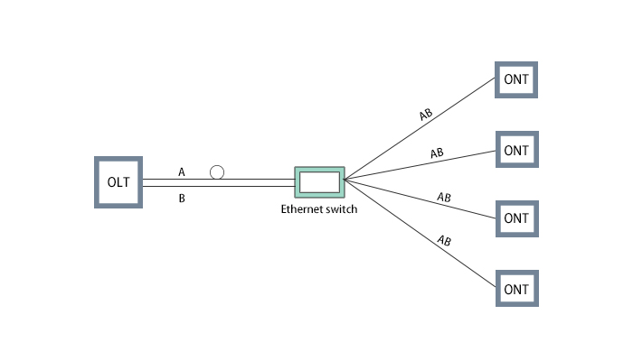
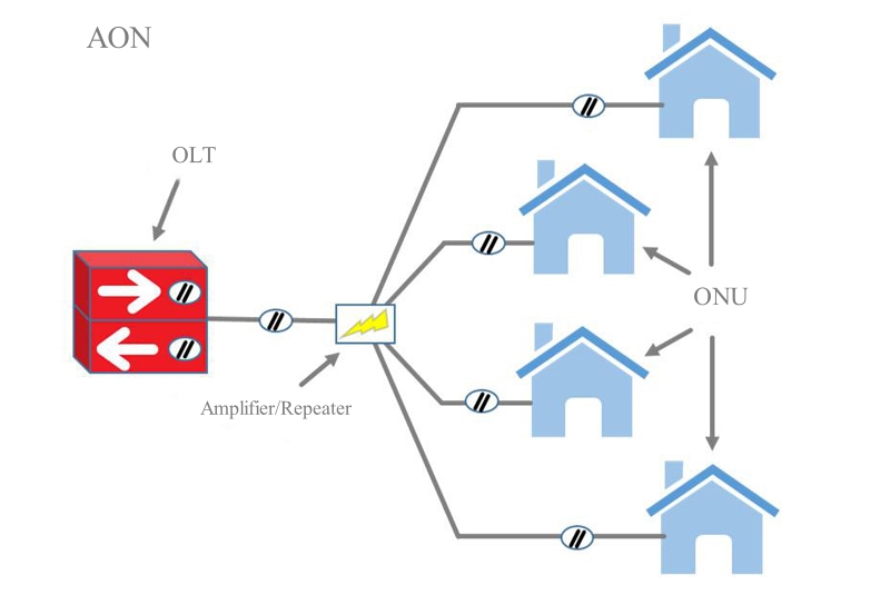
Active Optical Networks (AON) are point-to-point fiber access networks that rely on active devices like switches and routers for signal amplification and distribution. Unlike Passive Optical Networks (PON), AON uses active components to manage and handle optical signals, providing higher bandwidth and more flexible quality of service management.
In AON system, each user has a dedicated fiber connection to a central switch or router. The central device is responsible for distributing data to all users and receiving data uploaded from them. This point-to-point topology ensures that each user enjoys dedicated fiber bandwidth, avoiding the issues of bandwidth sharing common in other systems.
AON typically employs Ethernet technology, utilizing Ethernet switches for data forwarding and management. Due to the maturity and widespread use of Ethernet technology, AON systems are highly compatible and easy to use.
PON vs AON
Network Architectures
PON Architecture:
-
Point-to-Multipoint:PON uses a point-to-multipoint architecture where the Optical Line Terminal (OLT) distributes optical signals to multiple Optical Network Units (ONU) or Optical Network Terminals (ONT) via passive splitters. -
Passive Components:Splitters in PON are passive components that require no power supply or maintenance, reducing operational and maintenance costs. -
Centralized Management:PON operates with centralized management where all management and control functions are concentrated at the OLT, simplifying network management and configuration.
AON Architecture:
-
Point-to-Point:AON employs a point-to-point architecture where each user has an independent fiber connection to a central switch or router. -
Active Components:AON relies on active devices such as switches and routers to amplify and distribute signals, requiring power supply and regular maintenance. -
Distributed Management:AON uses distributed management where network management and control functions are spread across various active devices, providing higher flexibility and scalability.
Bandwidth
-
PON:Due to its point-to-multipoint structure, multiple users share the total bandwidth from the OLT. This can lead to bandwidth competition during peak times. Typical GPON systems offer a downstream rate of 2.5 Gbps and an upstream rate of 1.25 Gbps, while EPON systems have symmetric rates of 1 Gbps. -
AON:AON provides dedicated fiber bandwidth to each user, offering higher transmission rates and more stable performance. Ethernet AON can deliver bandwidths up to 10 Gbps or higher.
Latency
-
PON:The passive splitters in PON do not introduce additional latency. However, the Time Division Multiple Access (TDMA) mechanism in the upstream link might introduce some latency due to bandwidth sharing among multiple users. -
AON:Active devices in AON introduce some processing delay, but since each user has dedicated bandwidth, the overall latency is lower and more stable.
Transmission Distance
-
PON:The transmission distance in PON is limited to about 20 kilometers due to the insertion loss of passive splitters. Extending this distance is possible with the addition of repeaters but at an increased cost and complexity. -
AON:AON relies on active devices to amplify and relay signals, allowing for longer transmission distances suitable for extensive coverage areas.
Cost
-
PON:The use of passive components like splitters in PON reduces initial construction costs and operational expenses, making it suitable for large-scale deployments and cost-sensitive applications. -
AON:AON's use of active devices like switches and routers results in higher initial construction and operational costs, suitable for scenarios requiring high bandwidth and high service quality assurance.
Maintenance
-
PON:With no active devices in the middle network, passive components in PON require no maintenance, reducing operational and maintenance costs. -
AON:Active devices in AON require regular maintenance and power supply, increasing operational and maintenance costs but offering higher management flexibility and service quality assurance.
Application
PON:
-
Residential Broadband Access:PON's simple structure, low cost, and easy maintenance make it suitable for large-scale residential broadband access. -
Small and Medium Enterprise Access:For small and medium enterprises with moderate bandwidth needs, PON provides a cost-effective broadband access solution. -
Convergence of Voice, Video, and Data Services:PON supports multiple service types, suitable for scenarios requiring the integration of voice, video, and data.
AON:
-
Enterprise Broadband Access:AON offers high bandwidth, low latency, and high-quality service assurance, suitable for enterprise-level applications requiring high bandwidth and quality. -
Data Center Interconnection:AON's point-to-point architecture and high bandwidth capabilities make it ideal for high-speed interconnections between data centers. -
Long-Distance Transmission:AON can amplify and relay signals through active devices, suitable for scenarios requiring long-distance, high-bandwidth transmissions.