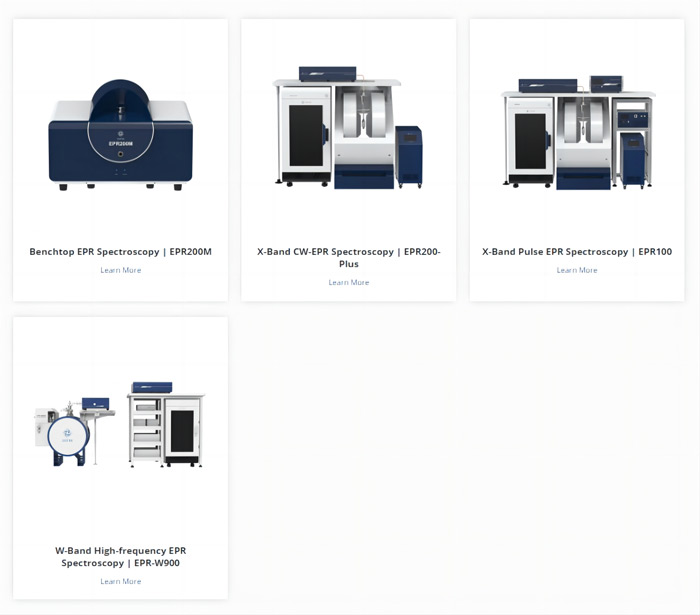
Some beginners of electron paramagnetic resonance (EPR) spectroscopy often face problems such as unclear basic principles, difficulty analyzing spectra, and unskilled operation of instruments.

To help our users better utilize EPR spectroscopy, CIQTEK launched this "EPR Mini-course" series to answer the problems encountered by users in their EPR studies and experiments.

Please feel free to email us at info@ciqtek.com for your specific questions.


Q1: An accessory used to determine orientation-dependent samples (e.g., single crystals) is a (   ).

A. Goniometer

B. Field/frequency lock system

C. Gaussmeter

D. Xenon lamp

------

Answer: A


Q2: The following options are important applications of high-frequency (e.g., W-band) EPR technology ( )?

A. Direct detection of living organisms 

B. To improve the sensitivity of detection of small numbers of samples [the same number as in low-frequency (e.g., X-band) detection].  

C. To improve spectral resolution

------

Answer: BC


Q3: True or False: For EPR testing, microwave power should be reduced before changing samples. 

------

Answer: True.

For EPR testing, make sure to reduce the microwave power to less than 40 dB. It is not permitted to remove the sample from the resonant cavity under high microwave power or to move the sample drastically, otherwise, serious detuning of the microwave bridge circuit may be caused, and the detector diode may even be burned out.


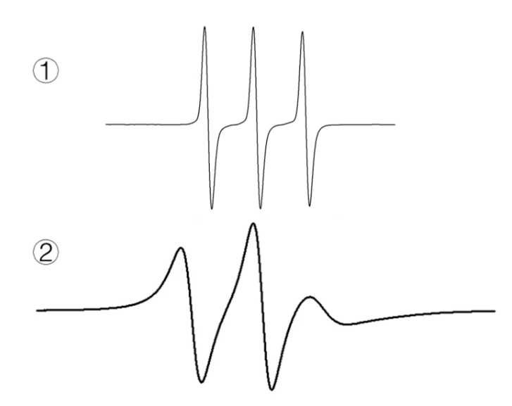
Q4: The viscosity of a solvent affects the rate of movement of the molecules, which in turn affects their EPR spectra. The figure below shows the EPR spectra of TEMPOL in water or glycerol system, the correct match is ( ). 

A. ①water system; ②glycerol system 

B. ①glycerol system; ②water system

EPR spectra of TEMPOL

------

Answer: A.

Glycerol is more viscous than water, and in the glycerol system, the motion of the TEMPOL molecules slows down and exhibits an anisotropic spectral signature.


This session is over. See you next time!

Electron paramagnetic resonance (EPR) spectroscopy is a powerful experimental technique for studying paramagnetic species' electronic structure and properties. In EPR spectroscopy, the g-value plays a crucial role in understanding the behavior and environment of unpaired electrons in paramagnetic systems. This article aims to provide an overview of g-values and their significance in EPR spectroscopy.


1. Understanding the g-value:

The g-value, the spectral splitting factor or Landé g-factor, describes the relationship between the magnetic field and the energy levels of unpaired electrons in a paramagnetic system. It determines the resonant frequency of the EPR signal and can be used to identify and characterize paramagnetic species.


2. The g-value formula:

The g-value is calculated using the following formula:


g = (hf)/(μB * B)


where


g is the spectral splitting factor

h is Planck's constant

f is the EPR signal frequency

μB is the Bohr magneton (physical constant)

B is the strength of the applied magnetic field

The g value depends on the magnitude and direction of the applied magnetic field and provides information about the electronic structure and its interaction with the magnetic field.


3. Significance of g-value:

a. Identification of paramagnetic species: The g-value is unique for each paramagnetic species and can be used to distinguish between different species. By comparing the experimentally measured g-value to a reference value, scientists can identify unknown paramagnetic species.


b. Detecting the electronic environment: The g-value is sensitive to the local electronic environment around unpaired electrons. Factors such as coordination field, coordination geometry, and the spin density of the unpaired electrons all affect the g-value. Analyzing changes in the g-value can provide insight into the electronic structure of a system and its surrounding environment.


c. Study of electron delocalization: In systems with multiple interacting unpaired electrons, the g-value provides information about the degree of electron delocalization. larger g-values indicate a higher degree of electron spin localization, while smaller g-values indicate a higher degree of electron localization.


d. Quantification of Magnetic Anisotropy: The g value helps in determining the degree of magnetic anisotropy, which is the dependence of the magnetic properties of a system on the direction of the applied magnetic field. g deviates from the free-electron value (2.0023) indicating the presence of an anisotropic factor.


4. Factors affecting the g value:

Several factors affect the g value, including the nature of the paramagnetic center, the coordination environment, the presence of neighboring atoms or molecules, and the effect of spin-orbit coupling. These factors add to the complexity of interpreting EPR spectra and require careful analysis and theoretical calculations.


The g value plays a fundamental role in EPR spectroscopy, providing valuable information about the electronic structure, environment, and magnetic properties of paramagnetic species. By understanding the significance of the g-value and its relation to the applied magnetic field, scientists can gain insight into the behavior and properties of unpaired electrons, thereby facilitating the characterization and study of various paramagnetic systems.


Check more EPR-related application notes


Check CIQTEK EPR series products.

Contact: info@ciqtek.com or check the Contact Page to leave us a message

EPR spectroscopy

Introduction

The digital revolution has brought the Internet of Things (IoT) into the fabric of our daily lives. Wi-SUN technology, celebrated for its robust performance and versatile applications, has become a favored option for large-scale IoT implementations. This article explores the Wi-SUN technology market, its main benefits, use cases and applications, and RF-stars implementation of Wi-SUN.

Wi-SUN Technology Market

Recent Wi-SUN Technology Market Research Report by Business Research Insight and Market Research Future indicate that the global Wi-SUN technology market, valued at USD 319.27 million in 2022, is predicted to reach USD 14.568 billion at a whopping 13.45% CAGR between 2024-2032. This surge is fueled by ongoing proliferation of smart meters, sensors, and IoT devices, as well as the accelerated digital transformation spurred by the COVID-19 pandemic. Notably, North America stands out as a region with significant adoption of Wi-SUN technology.

Wi-SUN Technology Market Size, 2023-2032

Figure1Wi-SUN Technology Market Size, 2023-2032 (USD Billion)

Source: https://www.marketresearchfuture.com/reports/wi-sun-technology-market-8695

Wi-SUN Overview

What is Wi-SUN?

Wi-SUN, or Wireless Smart Ubiquitous Network, is a wireless communication network based on the IEEE 802.15.4 standard. It delivers a high-performance, low-power, long-range, robust anti-interference, high data throughput, and highly secure wireless communication solution.

As a mesh network, it facilitates long-distance communication and high-data transmission between IoT devices through frequency-hopping and self-configuration technology. The network also features self-healing capability.

Wi-SUN: HAN vs. FAN

Wi-SUN supports two primary operational profiles: Home Area Network (HAN) and the Field Area Network (FAN):


  • HAN: Home Area Network HAN currently has several types, including Router B and enhanced HAN (supporting relay transmission). Router B refers to the Home Energy Management System (HEMS) controller, connecting smart appliances and smart meters. It enables real-time monitoring of smart appliance energy consumption and communication with FAN for smart city applications, enhancing the smart home environment.
  • FAN: Field Area Network Wi-SUN FAN is a mesh network where each device can establish multiple connections with nearby devices, scaling up to thousands of nodes. Each node provides typical long-distance hops. If an end-device fails to connect with another, it will automatically re-configure to an alternate path for other end-devices to the router node. This makes it ideal for large-scale infrastructure such as smart grids and streetlights. The Wi-SUN topology is illustrated below:
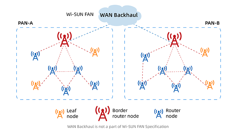

Wi-SUN network topology

Figure 2 Wi-SUN network topology

Benefits of Wi-SUN Network


  • Low Latency and High Data Throughput: Wi-SUN’s mesh topology, ensures a low-latency communication experience and supports high data throughput, catering to the demands of large-scale IoT deployments.
  • Low Power Consumption: Wi-SUN devices typically use battery power, significantly reducing energy consumption and extending device life.
  • Ease of Deployment and Scalability: Its straightforward network structure and support for self-forming networks make Wi-SUN an ideal choice for large-scale applications, with the flexibility to expand as the IoT ecosystem evolves.
  • High Security: Wi-SUN offers multiple layers of security mechanisms, such as advanced authentication, to ensure the safety of data transmission.
  • Interoperability: Based on the open standard IEEE 802.15.4, Wi-SUN supports data interoperability between end devices, enhancing overall network efficiency and application coverage.
  • Cost-Effectiveness: By integrating self-forming and adaptive frequency hopping technologies, Wi-SUN reduces overall costs, particularly suitable for in a wide range of IoT applications.
  • Wide Area Coverage: Using radio waves in the Sub-1GHz band (860MHz band, 920MHz band, and other bands below 1GHz), Wi-SUN offers longer reach and less radiofrequency interference with other electronic devices and obstacles. It is ideal for connecting utilities such as smart cities, smart homes, and energy management systems.


Wi-SUN Applications

Wi-SUN technology is finding its place in various global applications:

Smart Cities

Wi-SUN's long-distance transmission, scalability, bidirectional communication, and low power consumption have led to its deployment in many cities for smart meters and streetlights. For example, a Smart Cities Living Lab in Hyderabad, India, utilizes Wi-SUN mesh network technology to manage city assets efficiently.

Smart Streetlights

Wi-SUN technology supports large-scale outdoor IoT networks, including AMI metering and distribution automation, offering smart streetlight solutions for cities. In London, Wi-SUN mesh networks power streetlights, reducing maintenance costs and energy consumption while enhancing flexibility for aesthetic lighting and public safety.

Smart Meters

In smart cities, Wi-SUN technology enables real-time monitoring and management of electricity usage, optimizing energy distribution and reducing consumption.

Solar Power Plants

Wi-SUN networks allow for real-time monitoring of solar panel operations through intelligent monitoring systems, ensuring maximum power generation efficiency while minimizing environmental impact.

Smart Low Voltage Cabinets

In smart grids, Wi-SUN technology is used to deploy smart low-voltage cabinets, dynamically adjusting power supply and optimizing power distribution to enhance grid reliability and flexibility.

Industrial Facilities

Wi-SUN technology is also applied in the industrial and manufacturing sectors, providing non-proprietary solutions that make deployment more scalable, flexible, and secure.

RF-star Implementing Wi-SUN

As a global manufacturer of wireless modules, RF-star can supply a range of Wi-SUN modules based on TI CC1312 and CC1352 series chips.

Key Wi-SUN Modules

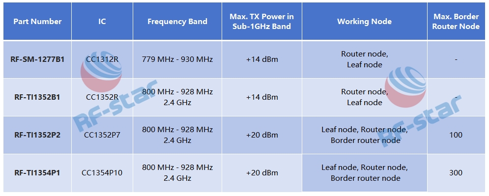
  • RF-SM-1277B1: Based on the CC1312R MCU, this low-power wireless module is designed for Sub-1GHz band from 779 MHz to 930 MHz.
  • RF-TI1352P2: Integrating a power amplifier, this module achieves a maximum transmit power of +20 dBm in the Sub-1 GHz band, offering a longer transmission distance and stronger penetration capability. Additionally, RF-TI1352P2 can operate in the 2.4 GHz band.

As shown below, the parameters of the Wi-SUN modules are listed:
RF-star’s Wi-SUN Modules

Figure 3 RF-stars Wi-SUN Modules

Upcoming Releases

In August, RF-star is set to launch a new Wi-SUN module based on the TI CC1354P10 SoC. This module is expected to be a multiprotocol and dual-band 800 MHz - 928 MHz and 2.4 GHz wireless module with 1024 kB Flash and 288 kB RAM. Notably, the RF-TI1354P1 module can operate as a border router, extending up to 300 nodes. This will provide robust support for large-scale, distributed IoT complex applications. Stay tuned!

Conclusion

Wi-SUN's unique mesh network architecture, combined with its low latency, high data throughput, low power consumption, ease of deployment and scalability, high security, interoperability, and long-range transmission capabilities, makes it an ideal solution for wide-area large-scale IoT applications. As the market for Wi-SUN continues to expand, its applications in smart cities, smart energy, and industrial IoT are growing, showcasing its potential to enhance connectivity efficiency, reduce costs, and improve user experience. With manufacturers like RF-star leading the development of high-performance Wi-SUN modules, the future of large-scale distributed IoT deployments looks promising.
In today's fast-paced digital world, the need for efficient and secure charging solutions for laptops, tablets, and Chromebooks has never been more critical. Introducing the LVSUN 16-Port USB-C Charging Cabinet, a cutting-edge innovation designed to streamline your device charging experience while prioritizing safety and organization.

Efficiency at its Best: The LVSUN charging cart is equipped with 16 USB-C ports featuring PD3.0 technology, ensuring rapid and reliable charging for up to 16 devices simultaneously. Say goodbye to tangled cords and slow charging speeds - with this advanced solution, you can power up your modern laptops and tablets in a fraction of the time.

Smart Control at Your Fingertips: With the "innovatecharger" app, managing your charging schedule has never been easier. Whether you're in a classroom, hospital, warehouse, factory floor, or office, you can remotely control the charging process from your phone, optimizing efficiency and convenience.

Safety First: The LVSUN charging cabinet is engineered with your safety in mind. Featuring ventilation systems, ground fault protection, and rounded corners, this charging station ensures a secure and worry-free charging experience. The perforated door and vented side panels facilitate proper airflow to prevent overheating, while the secure locking mechanism provides peace of mind knowing your devices are protected.

Versatile and Organized: Designed with a large storage area and interior dividers, this charging station accommodates Chromebooks, laptops, tablets, and more with ease. The cabinet's 180-degree opening door allows for convenient access to your devices, making charging and storage a seamless process.

In conclusion, the LVSUN 16-Port USB-C Charging Cabinet offers a comprehensive solution for all your charging needs. Enhance efficiency, security, and organization in various settings with this state-of-the-art technology. Experience the future of charging with LVSUN.

How much do you know about drone reconnaissance and jamming integrated equipment?


Drone reconnaissance and jamming integrated equipment is equipped with advanced sensors and detection technology, the system can identify and track drones within a specified range, providing real-time situational awareness to security personnel. Once a drone threat is detected, the system seamlessly transitions into strike mode, employing various countermeasures to neutralize the target.


With its compact and portable design, the system can be easily deployed in various environments. Its user-friendly interface and intuitive controls ensure quick and efficient operation by security personnel.


Here is a portable reconnaissance and jamming integrated anti-drone equipment from Beijing Kingfull Special Equipment Co., Ltd. This equipment is with the combination of reconnaissance and jamming function. Its main application scenarios including military control zones, urban counterterrorism, public security, judiciary, airports, ports, prisons, petrochemicals, power plants, nuclear power plants, border defense, and other important facilities' no-fly zones. It can also be used for major event security, anti-disclosure on law enforcement scene, anti-smuggling in border defense, and other occasions. Following are pictures of this equipment for your reference.

  • Portable reconnaissance and jamming integrated anti-drone equipment
  • Portable reconnaissance and jamming integrated anti-drone equipment
  • Portable reconnaissance and jamming integrated anti-drone equipment


If you are interested in this anti-UAV equipment or have any questions, please call 86-13381319816 or send email to sales@milikingfull.com. We welcome all your questions!


Laser technology plays a crucial role in various industries, ranging from telecommunications to medical applications. To ensure the optimal performance and longevity of lasers, regular maintenance and repair are essential. In this article, we will delve into the world of laser repair, with a specific focus on large diameter fusion splicers and laser maintenance. We will discuss the importance of these devices, common issues faced during repair, and some best practices for effective maintenance.


Understanding Large diameter Fusion Splicers:

Large diameter fusion splicers are specialized tools used in fiber optic communication systems for splicing or joining optical fibers. These splicers facilitate low-loss connections between fibers, ensuring efficient light transmission. During laser repair, working with large diameter fusion splicers is crucial to maintain the integrity of optical connections.


Common Issues and Troubleshooting:
Fiber Alignment: Misalignment of fibers can lead to signal loss or degradation. During laser repair, precise alignment is essential. Technicians must ensure optimal fiber positioning using visual feedback or automated alignment systems.
Arc Discharge and Electrode Contamination: Arc discharge in fusion splicers can cause electrode damage and contamination, affecting the splicing process. Regular cleaning and replacement of electrodes are necessary for proper laser repair.

Fusion Splice Loss: High splice loss can occur due to improper fiber preparation, fusion chamber contamination, or misalignment. Accurate fusion parameters, clean splicing environment, and careful fiber handling are crucial to minimize splice loss.


Laser Maintenance Best Practices:
Cleaning Procedures: Regular cleaning of lenses, mirrors, and fiber connectors is crucial to maintain laser performance. Specialized cleaning solutions, lint-free wipes, and proper handli
ng techniques should be employed to avoid damage.
Power Calibration and Alignment: Periodic power calibration and alignment checks ensure accurate laser output. Technicians should follow manufacturer guidelines and use appropriate power meters and alignment tools for precise measurements.

Cooling System Maintenance: Lasers generate heat, and proper cooling system maintenance is essential to prevent overheating. Regular inspection, cleaning of filters, and monitoring coolant levels and flow rates are necessary for optimal laser performance.


Importance of Professional Assistance:

Laser repair and maintenance are intricate processes that require specialized knowledge and expertise. Seeking professional assistance from certified technicians or service providers ensures effective diagnosis, troubleshooting, and repair, leading to longer laser lifespan and improved performance.


Effective laser repair and maintenance are vital for maximizing the lifespan and performance of large core fusion splicers and lasers. By understanding the common issues faced during repair, implementing best practices for maintenance, and seeking professional assistance when needed, industries can ensure the reliable and efficient operation of their laser systems. Remember, regular upkeep and timely repairs not only save time and money but also contribute to the overall productivity and success of various industries relying on laser technology.

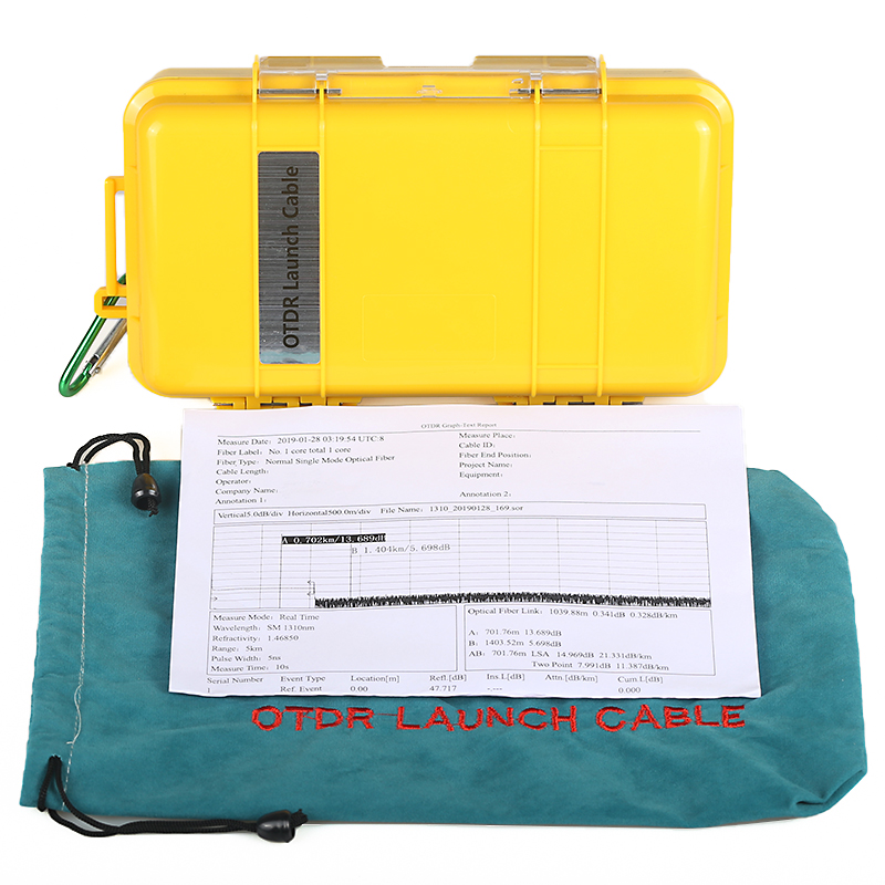
What's OTDR launch cable box / OTDR Dead Zone Eliminator used for?

An OTDR (Optical Time Domain Reflectometer) launch cable box, also known as an OTDR Dead Zone Eliminator, is used in fiber optic testing and troubleshooting.

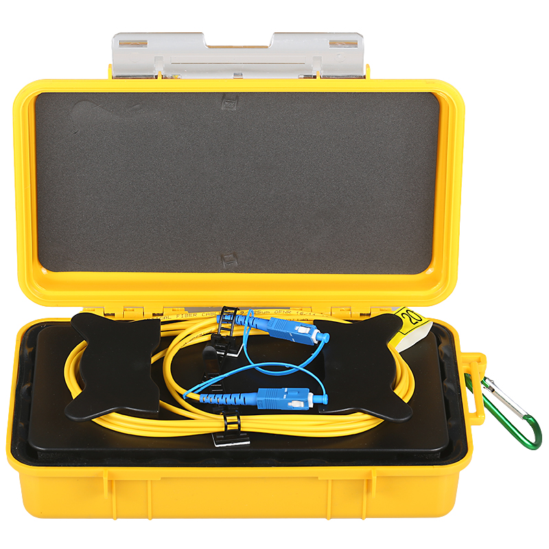
Launch Cable Box


In fiber optic testing, the OTDR is used to measure the characteristics of an optical fiber, such as loss, length, and quality. However, OTDRs have a limitation called the "dead zone," which is the distance from the OTDR launch point where it cannot accurately detect or measure events such as connectors, splices, or other reflective or non-reflective anomalies. The dead zone occurs due to the time it takes for the OTDR to recover after an initial pulse is transmitted.


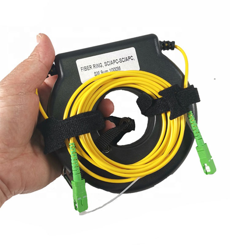
To overcome this dead zone limitation, an OTDR launch cable box is used. It is essentially a length of fiber optic cable with known characteristics and connectors, typically several kilometers long. The launch cable box is connected between the OTDR and the fiber under test.


The launch cable box helps eliminate the dead zone by allowing the OTDR to stabilize and recover from the initial pulse before encounters any reflective event. This enables the OTDR to provide more accurate measurements of the fiber's length, loss, and other characteristics beyond the dead zone. By using a launch cable box, it is possible to obtain more precise and reliable measurements of fiber optic networks, especially in the presence of short-distance reflective events.


Overall, the OTDR launch cable box or OTDR Dead Zone Eliminator plays a crucial role in improving the accuracy of fiber optic testing by minimizing the dead zone limitations of the OTDRs.


can do OEM for customers, and UPC/APC for option.  FC/SC/LC for option

Boxed OTDR Launch Cables UPC/APC


Boxed OTDR Launch Cables UPC/APC

Boxed OTDR Launch Cables UPC/APC

In the fast-paced digital era, where communication relies heavily on data transmission through optical fiber networks, maintaining the integrity and efficiency of these networks is paramount. Optical Time Domain Reflectometer (OTDR) is a crucial tool used in the maintenance and troubleshooting of these networks. This article explores the significance of OTDR in ensuring seamless communication and discusses its functions, advantages, and common applications.

OTDR, short for Optical Time Domain Reflectometer, is a specialized instrument used to characterize and troubleshoot optical fiber networks. It works on the principle of sending optical pulses into the fiber and analyzing the reflected light to determine various parameters such as loss, attenuation, and distance.
Key Functions of OTDR:
1 Optical Fiber Fault Detection: OTDR helps in locating and identifying faults, such as fiber breaks, bends, or excessive losses along the fiber optic cable. By analyzing the time and intensity of the reflected light, it accurately pinpoints the exact location of the fault.
2 Fiber Length Measurement: OTDR measures the length of the fiber optic cable accurately. This information is crucial for estimating the overall distance covered by the cable and ensuring proper network planning.
3 Fiber Attenuation Measurement: By analyzing the strength of the reflected light, OTDR can determine the amount of signal loss (attenuation) experienced by the optical fiber. It helps in assessing the overall health and performance of the network.
4 Fiber Characterization: OTDR provides a comprehensive analysis of the optical fiber characteristics, including the splice loss, connector loss, and nonlinear effects. This information enables technicians to optimize the network's performance and identify potential issues.
Advantages of OTDR:
1 Precision and Accuracy: OTDR offers high precision and accuracy in measuring parameters such as loss and distance, providing reliable data for network analysis.
2 Time Efficiency: By combining multiple functions in a single instrument, OTDR saves time and effort in network troubleshooting and maintenance.
3 Non-Destructive Testing: OTDR performs non-destructive testing, meaning it does not interfere with normal network operations when examining the optical fiber cable.
Common Applications of OTDR:
1 Network Installation and Maintenance: OTDR plays a crucial role in network deployment, verifying proper installation and ensuring the fiber's integrity and performance.
2 Fiber Optic Link Characterization: OTDR helps in characterizing optical fiber links by measuring the fiber length, attenuation, and identifying potential issues such as high splice or connector losses.
3 Fault Location and Troubleshooting: OTDR assists technicians in locating and diagnosing fiber optic faults, reducing downtime and improving network reliability.
4 Fiber Network Upgrade and Expansion: OTDR is used to assess the viability of installing additional network equipment and expanding the existing fiber infrastructure.

In today's interconnected world, where optical fiber networks form the backbone of communication systems, the role of OTDR in network maintenance cannot be understated. By accurately detecting faults, measuring distances, and characterizing fiber links, OTDR ensures the smooth operation and optimal performance of these networks. Its precision, efficiency, and versatile applications make it an indispensable tool for technicians involved in optical fiber network maintenance.

Polarization-maintaining fiber (PMF) fusion splicers play a crucial role in the field of communications. These specialized machines are designed to precisely align and fuse polarization-maintaining fibers, ensuring the integrity of the transmitted optical signals. However, like any equipment, PMF fusion splicers require regular maintenance and occasional repairs to maintain their optimal performance. This article aims to provide an overview of PMF fusion splicer maintenance, highlighting key aspects and best practices.


Cleaning and Inspection:

One of the fundamental maintenance tasks for PMF fusion splicers is regular cleaning and inspection. Dust, dirt, and debris can adversely affect splicing quality and compromise the polarization-maintaining properties of the fiber. It is essential to clean the fusion splicer's optics, V-grooves, and electrodes using lint-free wipes and alcohol-based cleaning solutions. Additionally, inspecting the fusion splicer for any signs of damage or wear ensures early detection of potential issues.


Calibration and Alignment:

As PMF fusion splicers require high precision alignment between the fibers, regular calibration and alignment checks are crucial. The fusion splicer should be calibrated according to the manufacturer's guidelines to ensure accurate fusion and minimize signal losses. Aligning the fusion splicer's optical axes, evaluating the polarization extinction ratio (PER), and optimizing the fusion parameters are critical steps to maintain the optimum performance of the splicer.


Electrode Maintenance and Replacement:

The electrodes of PMF fusion splicers can degrade over time due to repeated use and arc discharges during the fusion process. Regular inspection of the electrodes is necessary, and if any signs of pitting or contamination are observed, they should be cleaned or replaced promptly. Maintaining clean and well-aligned electrodes ensures consistent and reliable splicing results.


Software and Firmware Updates:

Manufacturers often release software and firmware updates for PMF fusion splicers to improve their functionality and address any known issues. It is essential to keep the splicer's software and firmware up-to-date by regularly checking for updates on the manufacturer's website. Updating to the latest version can enhance the performance, stability, and compatibility of the fusion splicer.


Proper Handling and Transportation:
Proper handling and transportation of PMF fusion splicers are crucial to prevent physical damage. Avoid exposing the splicer to extreme temperature and humidity conditions, and ensure secure packaging and adequate cushioning during transportation. Following the manufacturer's guidelines for safe handling and transportation ensures the longevity of the machine.

Maintenance plays a vital role in maximizing the longevity and performance of polarization-maintaining fiber fusion splicers. Regular cleaning, inspection, calibration, and alignment are essential tasks to ensure optimal splicing quality and preserve the polarization-maintaining characteristics of the fiber. Additionally, promptly addressing any electrode issues, staying updated with software and firmware, and observing proper handling practices are critical for effective PMF fusion splicer maintenance. By following these best practices, technicians can ensure the reliable operation of the equipment and maintain the efficient functioning of polarization-maintaining fiber-based optical systems.