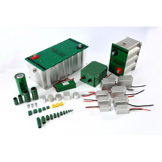
Hermetically Sealed High Energy Tantalum Capacitor is high-performance, high-energy density, low impedance and full sealing. With the innovative multi-anode parallel structure, the self-impedance of the capacitor is significantly reduced, resulting in lower heat generation and higher reliability during high-power-density charging and discharging. Additionally, it can be used in circuits with some AC components for discharging and dual-purpose filtering as a filter and power compensation device.
To ensure high reliability during usage, please take note of the following points.
1. Test
1.1 Hermetically Sealed High Energy Tantalum Capacitor is a polar component, the polarity must not be reversed during use and testing. If the polarity is reversed, the reliability of the capacitor will be irreversibly damaged and cannot be used anymore.
1.2 Capacitance & Dissipation Factor Measuring Conditions: 1.0Vrms@100Hz
1.3 Equivalent Series Resistance(ESR):measuredat1000Hz,1Vrms
1.4 Leakage current test: Apply rated voltage or class voltage for 5min. The qualified standards for leakage current can be found in the product specifications and corresponding specifications.
1.5 Professional testing instruments and fixtures must be used. A multimeter cannot be used to test any parameters of hermetically sealed high energy tantalum capacitor. It is not possible to use a multimeter to test it regardless of polarity.
1.6 Hermetically sealed high energy tantalum capacitor can store a high amount of electrical energy, after conducting a leakage current test, the capacitor must be thoroughly discharged by a standard leakage current tester before use.
Discharge resistance: 1000 ohms;
Discharge time: ≥ 5mins
Residual voltage after discharge:<1V
1.7 Test of electrical performance must be carried out in the following order and cannot violate.
Test sequence: Capacitance & Dissipation Factor - ESR - Leakage Current – Discharge
2. Precautions for use on different circuits
2.1 Delay protection circuit
The capacitors used in such circuits primarily serve as backup power for unexpected power outages, requiring them to automatically engage when the main power source suddenly fails. They must maintain a specified power supply duration under certain voltage and power density requirements. When designing circuits of this nature, please pay attention to the mathematical relationship between the total impedance of the capacitor's downstream circuit and the required voltage, capacitor capacity, and power needs. Additionally, during the design phase, it is advisable to leave at least a 50% margin in capacitor capacity selection to ensure that there is enough power supply time and power density in case of unforeseen factors. The specific calculation is as follows:
When the circuit is working normally,
Input power: P
Capacitance: C
Voltage at both ends: U1
Then, the energy stored by the capacitor is
W1=C(U12)/2
Where U12 represents the square of U1.
When the input power supply drops out, after a time t, the voltage at both ends U2,
Then, the remaining energy of the capacitor is
W2=C(U22)/2
The energy released during this process:
W=W1-W2=C(U12-U22)/2
It should be equal to the energy required to keep the circuit working properly:
W=Pt(i.e. input power multiplied by time)
Therefore,
C(U12-U22)/2=Pt
From this, the minimum capacitance required for the circuit maintenance time t can be obtained as:
C=2Pt/(U12-U22)
In practical applications, U2 is the minimum input voltage that a circuit can operate normally.
Example:
If when the circuit is working normally, the input voltage is 28V (U1), the input power is 30W (P), and the minimum input voltage that can work normally is 18V (U2). It is required that the circuit can still work even after a 50 millisecond (t) power drop-out from the input power supply, then the minimum capacitance required for energy storage capacitance is
C=2Pt/(U12-U22)
=2×30×50/(282-182)
=3000/(784-324)
=6.522mF=6522μF
An energy storage capacitor used in the front end of a power supply circuit has an input voltage of 50 V. When the power is cut off, the capacitor begins to supply energy to the subsequent circuit, and the voltage must be maintained at not less than 18 V while supplying energy for 75 W. Calculate the required capacitance.
This circuit also requires an accurate loop resistance. The size of the circuit resistance determines the required capacity of the capacitor.
The conversion formula for the performance of each parameter in this circuit is as follows:
C=R×PT×T/(U1-U2)
In the equation:
C: Required capacitance (F)
R: Total circuit resistance (Ω)
Pt: The power that the circuit needs to maintain (W)
T: Loop power holding time (s)
U1: Input voltage (V)
U2: Voltage that can maintain a certain power and discharge time (V)
The capacitor used in such circuits must be derated to within 70% of the rated voltage.
2.2 Charging and discharging circuit
Due to its high energy density and low impedance characteristics, this capacitor is the best choice for high-power discharge circuits. The hermetically sealed high energy tantalum capacitor used in such circuits can still achieve high power density infinite charging and discharging under certain conditions and still has high reliability. It is the best instantaneous power supply.
In such circuits, the relationship among the capacitance of capacitors, the output power density and load power can be calculated by referring to clause 2.1.
In this type of circuit, the maximum discharge current I to which the capacitor can be subjected individually must not exceed 50% of the current value calculated in the following formula;
Due to the inherent thermal equilibrium issue that capacitors inevitably face during high-power discharges, the maximum DC current pulse that tantalum capacitors can safely withstand in a DC high-power discharge circuit with a fixed impedance is determined by the following formula:
I=UR /(R+ESR)
In the equation:
I: Maximum DC surge current (A)
R: The total impedance of the circuit for testing or discharging (Ω)
UR: Rated voltage (V)
ESR: Equivalent series resistance (Ω)
From the above formula, it can be observed that if a product has a higher ESR (Equivalent Series Resistance), its safe DC surge current capability will be reduced. This also implies that if one product has half the ESR of another, its resistance to DC surge will be twice as high, and its filtering characteristics will be better as well.
When using capacitors in such circuits, since the capacitors operate continuously at high power levels, the actual operating voltage should not exceed 70% of the rated voltage. Considering the impact of heat dissipation on reliability, it is even better to derate the usage to below 50% for higher reliability.
Furthermore, when using this type of capacitor in such circuits, due to the high operating current, the capacitor will experience some heating. When designing the capacitor's placement, it is essential to ensure that it is not positioned too close to other heat-sensitive components. Additionally, the installation space for this capacitor must have good ventilation.
2.3 Filtering and power compensation for the power supply secondary
The allowable AC ripple value of the capacitor used in such circuits must be strictly controlled. Otherwise, excessive AC ripple can lead to significant heating of the capacitor and reduced reliability. In principle, the maximum allowable AC ripple value should not exceed 1% of the rated voltage, the current should not exceed 5% of the maximum permissible discharge current, and the maximum allowable operating voltage of the capacitor should not exceed 50% of the rated voltage.
3. Derating design of hermetically sealed high energy tantalum capacitor
In general, the reliability of capacitors is closely related to the operating conditions of the circuit. To ensure an adequate level of reliability during usage, it is essential to adhere to the following principles:
3.1 Reduce more rather than less
Because the greater the derating of capacitors, the higher the reliability in handling unexpected power shocks. Additionally, derating design should be based on reliability under possible extreme usage conditions, such as high operating temperatures, high ripple currents, and significant temperature and power fluctuations.
3.2 Select large capacity rather than small
The larger the capacitance, the higher the instantaneous electrical energy it can provide. Additionally, since this capacitor falls under the basic category of tantalum electrolytic capacitors, it experiences greater capacity loss at low temperatures (compared to solid tantalum capacitors). Therefore, the capacity selection should be based on the capacity at extreme negative temperatures. This is particularly important for capacitors used at high altitudes. Specific capacity variations at low temperatures can be found in the product specifications and relevant standards.
3.3 Selection of Impedance
For circuits used in situation 2.3, it is essential to choose products with a lower ESR whenever possible for higher reliability and improved filtering performance.
3.4 Selection of Capacitor Size
Due to the fact that smaller products with the same capacity and voltage must be manufactured using tantalum powder with higher specific capacity, the ESR of the product will be higher, and the leakage current will also be greater. Therefore, the reliability of the product will be lower than that of larger products. When installation space allows, products with larger volumes should be used as much as possible to achieve higher reliability.
4. Installation
4.1 Installation ways
The positive lead wire of hybrid energy tantalum capacitors cannot be directly welded to the circuit board, but must be welded to the circuit board through the external lead wire. High energy tantalum composite will be present.
There are three ways to install the circuit board, as shown below:
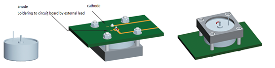
Figure 1:Installation mode of single negative pole lead (fixed by mounting frame)
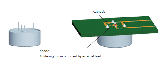
Figure 2:Double negative or triple negative lead installation mode (fixed by negative lead)
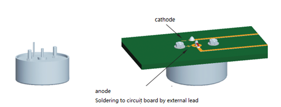
Figure 3:Double screw or triple screw installation (fixed by screw)
4.2 Considerations for Installation Method Selection
Due to the relatively large mass and size of this capacitor, it is advisable to adhere to the following principles during installation:
(a)For specifications with large size and mass, standard mounting brackets provided by the manufacturer should be used as much as possible to ensure that the connection between the product and circuit will not experience instantaneous open circuits when the equipment encounters large vibrations and overload impacts, and also to ensure installation strength requirements.
(b) For conditions where size and mass are relatively small and there are stringent requirements for installation space, capacitor products with built-in mounting bolts can be used. For such installations, it is essential to ensure that the circuit board has a high level of strength. Additionally, after tightening the mounting bolts, epoxy-based sealant must be used to secure the bolts. If conditions allow, other forms of fastening (such as applying adhesive to the capacitor base) can also be employed to ensure that the capacitor's mounting strength meets the requirements for extreme conditions of use.
(c) For products used in high-power continuous discharge circuits, capacitors should not be installed too close to devices with significant heat dissipation to prevent the capacitor from overheating and experiencing reduced reliability. Additionally, capacitors used in such circuits should not have heat-insulating sealant coatings applied to their casings to avoid a decrease in heat dissipation performance, which could lead to increased temperatures and reduced reliability of the capacitors.
(d) For products used in high-power uninterrupted discharge circuits, it is essential to have good ventilation conditions to ensure that the heat generated by the capacitors can be promptly expelled, preventing excessive temperature rise of the capacitors.
(e) The anode lead of hermetically sealed high energy tantalum capacitor is connected to the casing with an insulating ceramic material. Therefore, during installation, the positive lead that is fixed to the circuit board must be connected using nickel-based leads that are soldered on; it is not permissible to directly solder the excessively short tantalum leads onto the circuit board. This is because short positive leads can compromise the capacitor's seal when subjected to high overload and high-frequency vibrations, leading to leakage and capacitor failure.
5. Circuit protection
5.1 If the selected capacitor operates at a frequency with significant power variations, it is advisable to implement overload protection in the power supply circuit providing energy compensation to the capacitor. This helps prevent overloading of the power supply when there is a sudden surge in starting current.
5.2 The circuit in which this capacitor is used must have reverse voltage control and a separate discharge path to prevent the capacitor from experiencing reverse surges during operation and shutdown. The energy stored in the capacitor should be correctly discharged after use.