1. Ceramic chip capacitor failure caused by external force

(1) Because the ceramic chip capacitor is brittle and has no pin, it is greatly affected by the force. Once it is affected by the external force, the internal electrode is easy to break, resulting in the failure of the ceramic chip capacitor. As shown in Figures below, the capacitor end of ceramic patch is broken or damaged due to any external force. For example, in the process of mechanical assembly, the printed circuit board assembly is installed in the box, and the electric driver is used for assembly. At this time, the mechanical stress of the electric driver is easy to disconnect the capacitor. 


(2) Due to the quality problem of poor bonding force of ceramic chip capacitor end (body and electrode), the metal electrode is easy to fall off through the process of welding, warm punching, debugging and other external forces, that is, the body and electrode are separated, as shown in Figure as below.


 2. Failure caused by improper welding operation


(1) It is very common that the thermal shock of ceramic chip capacitor caused by improper manual welding or rework of electric iron.

When welding, there will be thermal shock. If the operator contacts the tip of the soldering iron directly with the electrode of the capacitor, the thermal shock will cause the micro crack of the ceramic chip capacitor body, and the ceramic chip capacitor will fail after a period of time. In principle, the SMT should be welded by hand. Multiple welding, including rework, will also affect the solderability of the chip and the resistance to welding heat, and the effect is cumulative, so it is not suitable for the capacitor to be exposed to high temperature for many times


(2) The tin on both ends of the capacitor is asymmetric during welding.When welding, the tin on both ends of the capacitor is asymmetric, as shown in below figure.

The tin on both ends of the capacitor is asymmetric. When the capacitor is subjected to external force or stress screening test, the ceramic patch will be seriously affected due to excessive soldering. The capacitor's ability to resist mechanical stress will lead to cracking of the body and electrode and failure.


(3) Too much solder

The factors related to the degree of mechanical stress of multilayer ceramic chip capacitor on PCB include the material and thickness of PCB, the amount of solder and the position of solder. Especially, too much solder will seriously affect the ability of chip capacitor to resist mechanical stress, resulting in capacitor failure.


3. Capacitor failure caused by unreasonable pad design

(1) The design of the pad is unreasonable, as shown in below Figure, when there is a hole in the pad. Solder will lose (there is such design phenomenon in the product), which causes welding defects due to the asymmetry of solder at both ends of capacitor. At this time, stress screening or external force will be conducted. The stress released at both ends of ceramic chip capacitor will easily cause cracking and failure.


(2) Another pad design is shown in below Figure. When using on-line welding, the size of pads at both ends of the capacitor is different or asymmetric (this design phenomenon exists in the product), the amount of solder paste printed is quite different. The small pad has a fast response to temperature, and the solder paste on it melts first. Under the action of solder paste tension, the component is straightened up, resulting in "upright" phenomenon or solder asymmetry, causing capacitor failure. One end of several ceramic chip capacitors share a large pad. If one capacitor at the common end needs to be repaired or one of the capacitors fails and needs to be replaced, one end of the other components will also experience a thermal shock, and the capacitor is prone to failure.


4. Failure caused by high and low temperature impact test

During the test, the thermal expansion coefficient (CTE) of PCB, MLCC end electrode and ceramic dielectric is small, and the chip capacitor is subjected to certain thermal stress due to the rapid change of cold and hot. The body (ceramic) and electrode (metal) of SMC produce stress cracks, which lead to the failure of SMC.


5. Failure caused by mechanical stress

Improper operation of the printing plate in the assembly process will cause mechanical stress, which will lead to capacitor rupture, and the pad is designed near the screw hole, which is easy to cause mechanical damage during assembly. This kind of damage makes the crack expand further in the temperature shock test, which leads to the capacitor failure. It can be seen from the structure that MLCC can withstand large compressive stress, but its bending resistance is poor. Any operation that may produce bending deformation during capacitor assembly will lead to component cracking.


Hermetically Sealed High Energy Tantalum Capacitor is high-performance, high-energy density, low impedance and full sealing. With the innovative multi-anode parallel structure, the self-impedance of the capacitor is significantly reduced, resulting in lower heat generation and higher reliability during high-power-density charging and discharging. Additionally, it can be used in circuits with some AC components for discharging and dual-purpose filtering as a filter and power compensation device.


To ensure high reliability during usage, please take note of the following points.


1. Test


1.1 Hermetically Sealed High Energy Tantalum Capacitor is a polar component, the polarity must not be reversed during use and testing. If the polarity is reversed, the reliability of the capacitor will be irreversibly damaged and cannot be used anymore.


1.2 Capacitance & Dissipation Factor Measuring Conditions: 1.0Vrms@100Hz


1.3 Equivalent Series ResistanceESR):measuredat1000Hz,1Vrms


1.4 Leakage current test: Apply rated voltage or class voltage for 5min. The qualified standards for leakage current can be found in the product specifications and corresponding specifications.


1.5 Professional testing instruments and fixtures must be used. A multimeter cannot be used to test any parameters of hermetically sealed high energy tantalum capacitor. It is not possible to use a multimeter to test it regardless of polarity.


1.6 Hermetically sealed high energy tantalum capacitor can store a high amount of electrical energy, after conducting a leakage current test, the capacitor must be thoroughly discharged by a standard leakage current tester before use.

Discharge resistance: 1000 ohms;

Discharge time: 5mins

Residual voltage after discharge:<1V


1.7 Test of electrical performance must be carried out in the following order and cannot violate.

Test sequence: Capacitance & Dissipation Factor - ESR - Leakage Current – Discharge


2. Precautions for use on different circuits


2.1 Delay protection circuit

The capacitors used in such circuits primarily serve as backup power for unexpected power outages, requiring them to automatically engage when the main power source suddenly fails. They must maintain a specified power supply duration under certain voltage and power density requirements. When designing circuits of this nature, please pay attention to the mathematical relationship between the total impedance of the capacitor's downstream circuit and the required voltage, capacitor capacity, and power needs. Additionally, during the design phase, it is advisable to leave at least a 50% margin in capacitor capacity selection to ensure that there is enough power supply time and power density in case of unforeseen factors. The specific calculation is as follows:


When the circuit is working normally,

Input power: P

Capacitance: C

Voltage at both ends: U1

Then, the energy stored by the capacitor is

 W1=CU12/2

Where U12 represents the square of U1.

When the input power supply drops out, after a time t, the voltage at both ends U2,

Then, the remaining energy of the capacitor is

W2=CU22/2

The energy released during this process:

W=W1-W2=CU12-U22/2

It should be equal to the energy required to keep the circuit working properly:

W=Pti.e. input power multiplied by time

Therefore,

CU12-U22/2=Pt

From this, the minimum capacitance required for the circuit maintenance time t can be obtained as:

C=2Pt/U12-U22

In practical applications, U2 is the minimum input voltage that a circuit can operate normally.


Example:

If when the circuit is working normally, the input voltage is 28V (U1), the input power is 30W (P), and the minimum input voltage that can work normally is 18V (U2). It is required that the circuit can still work even after a 50 millisecond (t) power drop-out from the input power supply, then the minimum capacitance required for energy storage capacitance is


C=2Pt/U12-U22

 =2×30×50/282-182

 =3000/784-324

 =6.522mF=6522μF


An energy storage capacitor used in the front end of a power supply circuit has an input voltage of 50 V. When the power is cut off, the capacitor begins to supply energy to the subsequent circuit, and the voltage must be maintained at not less than 18 V while supplying energy for 75 W. Calculate the required capacitance.

This circuit also requires an accurate loop resistance. The size of the circuit resistance determines the required capacity of the capacitor.

The conversion formula for the performance of each parameter in this circuit is as follows:

C=R×PT×T/(U1-U2)


In the equation:


C: Required capacitance (F)

R: Total circuit resistance (Ω)

Pt: The power that the circuit needs to maintain (W)

T: Loop power holding time (s)

U1: Input voltage (V)

U2: Voltage that can maintain a certain power and discharge time (V)

The capacitor used in such circuits must be derated to within 70% of the rated voltage.


2.2 Charging and discharging circuit

Due to its high energy density and low impedance characteristics, this capacitor is the best choice for high-power discharge circuits. The hermetically sealed high energy tantalum capacitor used in such circuits can still achieve high power density infinite charging and discharging under certain conditions and still has high reliability. It is the best instantaneous power supply.


In such circuits, the relationship among the capacitance of capacitors, the output power density and load power can be calculated by referring to clause 2.1.


In this type of circuit, the maximum discharge current I to which the capacitor can be subjected individually must not exceed 50% of the current value calculated in the following formula;

Due to the inherent thermal equilibrium issue that capacitors inevitably face during high-power discharges, the maximum DC current pulse that tantalum capacitors can safely withstand in a DC high-power discharge circuit with a fixed impedance is determined by the following formula:


I=UR /R+ESR


In the equation:


I: Maximum DC surge current (A)

R: The total impedance of the circuit for testing or discharging (Ω)

UR: Rated voltage (V)

ESR: Equivalent series resistance (Ω)


From the above formula, it can be observed that if a product has a higher ESR (Equivalent Series Resistance), its safe DC surge current capability will be reduced. This also implies that if one product has half the ESR of another, its resistance to DC surge will be twice as high, and its filtering characteristics will be better as well.

When using capacitors in such circuits, since the capacitors operate continuously at high power levels, the actual operating voltage should not exceed 70% of the rated voltage. Considering the impact of heat dissipation on reliability, it is even better to derate the usage to below 50% for higher reliability.

Furthermore, when using this type of capacitor in such circuits, due to the high operating current, the capacitor will experience some heating. When designing the capacitor's placement, it is essential to ensure that it is not positioned too close to other heat-sensitive components. Additionally, the installation space for this capacitor must have good ventilation.


2.3 Filtering and power compensation for the power supply secondary 

The allowable AC ripple value of the capacitor used in such circuits must be strictly controlled. Otherwise, excessive AC ripple can lead to significant heating of the capacitor and reduced reliability. In principle, the maximum allowable AC ripple value should not exceed 1% of the rated voltage, the current should not exceed 5% of the maximum permissible discharge current, and the maximum allowable operating voltage of the capacitor should not exceed 50% of the rated voltage.


3. Derating design of hermetically sealed high energy tantalum capacitor


In general, the reliability of capacitors is closely related to the operating conditions of the circuit. To ensure an adequate level of reliability during usage, it is essential to adhere to the following principles:

3.1 Reduce more rather than less

Because the greater the derating of capacitors, the higher the reliability in handling unexpected power shocks. Additionally, derating design should be based on reliability under possible extreme usage conditions, such as high operating temperatures, high ripple currents, and significant temperature and power fluctuations.


3.2 Select large capacity rather than small

The larger the capacitance, the higher the instantaneous electrical energy it can provide. Additionally, since this capacitor falls under the basic category of tantalum electrolytic capacitors, it experiences greater capacity loss at low temperatures (compared to solid tantalum capacitors). Therefore, the capacity selection should be based on the capacity at extreme negative temperatures. This is particularly important for capacitors used at high altitudes. Specific capacity variations at low temperatures can be found in the product specifications and relevant standards.


3.3 Selection of Impedance

For circuits used in situation 2.3, it is essential to choose products with a lower ESR whenever possible for higher reliability and improved filtering performance.


3.4 Selection of Capacitor Size

Due to the fact that smaller products with the same capacity and voltage must be manufactured using tantalum powder with higher specific capacity, the ESR of the product will be higher, and the leakage current will also be greater. Therefore, the reliability of the product will be lower than that of larger products. When installation space allows, products with larger volumes should be used as much as possible to achieve higher reliability.


4. Installation


4.1 Installation ways 

The positive lead wire of hybrid energy tantalum capacitors cannot be directly welded to the circuit board, but must be welded to the circuit board through the external lead wire. High energy tantalum composite will be present.

There are three ways to install the circuit board, as shown below:

Figure 1Installation mode of single negative pole lead (fixed by mounting frame)


 Figure 2Double negative or triple negative lead installation mode (fixed by negative lead)


Figure 3Double screw or triple screw installation (fixed by screw)


4.2 Considerations for Installation Method Selection 

Due to the relatively large mass and size of this capacitor, it is advisable to adhere to the following principles during installation:

aFor specifications with large size and mass, standard mounting brackets provided by the manufacturer should be used as much as possible to ensure that the connection between the product and circuit will not experience instantaneous open circuits when the equipment encounters large vibrations and overload impacts, and also to ensure installation strength requirements.

(b) For conditions where size and mass are relatively small and there are stringent requirements for installation space, capacitor products with built-in mounting bolts can be used. For such installations, it is essential to ensure that the circuit board has a high level of strength. Additionally, after tightening the mounting bolts, epoxy-based sealant must be used to secure the bolts. If conditions allow, other forms of fastening (such as applying adhesive to the capacitor base) can also be employed to ensure that the capacitor's mounting strength meets the requirements for extreme conditions of use.

(c) For products used in high-power continuous discharge circuits, capacitors should not be installed too close to devices with significant heat dissipation to prevent the capacitor from overheating and experiencing reduced reliability. Additionally, capacitors used in such circuits should not have heat-insulating sealant coatings applied to their casings to avoid a decrease in heat dissipation performance, which could lead to increased temperatures and reduced reliability of the capacitors.

(d) For products used in high-power uninterrupted discharge circuits, it is essential to have good ventilation conditions to ensure that the heat generated by the capacitors can be promptly expelled, preventing excessive temperature rise of the capacitors.

(e) The anode lead of hermetically sealed high energy tantalum capacitor is connected to the casing with an insulating ceramic material. Therefore, during installation, the positive lead that is fixed to the circuit board must be connected using nickel-based leads that are soldered on; it is not permissible to directly solder the excessively short tantalum leads onto the circuit board. This is because short positive leads can compromise the capacitor's seal when subjected to high overload and high-frequency vibrations, leading to leakage and capacitor failure.


5. Circuit protection


5.1 If the selected capacitor operates at a frequency with significant power variations, it is advisable to implement overload protection in the power supply circuit providing energy compensation to the capacitor. This helps prevent overloading of the power supply when there is a sudden surge in starting current.

5.2 The circuit in which this capacitor is used must have reverse voltage control and a separate discharge path to prevent the capacitor from experiencing reverse surges during operation and shutdown. The energy stored in the capacitor should be correctly discharged after use.


Digital signage LED walls refer to large-scale displays made of multiple LED panels or modules arranged in a grid-like configuration to create a seamless and immersive visual display. These LED walls are used for advertising, information dissemination, and entertainment purposes in various indoor and outdoor locations.


LED walls offer several advantages over traditional signage methods:


1. Brightness and Visibility: LED walls are highly luminous, ensuring excellent visibility even in brightly lit environments. They can produce vibrant and eye-catching visuals that attract attention.


2. Scalability: LED walls are modular, allowing for easy expansion or reduction in size as per the specific requirements of the display space. Additional LED panels can be seamlessly integrated to increase the wall's size or resolution.


3. Seamless Integration: LED panels are designed to fit together seamlessly, creating a uniform display surface without visible gaps. This ensures that the content appears cohesive and continuous across the entire wall.


4. Flexibility in Content Display: LED walls can display a wide range of content types, including static images, videos, animations, text, and interactive elements. They provide flexibility in content management and can easily be updated and scheduled remotely.


5. Durability and Longevity: LED walls are built using robust materials, making them resistant to environmental factors such as dust, moisture, and temperature variations. They have a longer lifespan compared to other display technologies.


6. Energy Efficiency: LED technology is energy-efficient, consuming less power than traditional display methods. This can result in cost savings in the long run and lower environmental impact.


7. Dynamic and Engaging Experience: LED walls offer a dynamic and immersive visual experience. Their large size and high resolution allow for impactful storytelling and engaging interactions with the audience.


Overall, digital signage LED walls provide a versatile and visually captivating solution for advertising, information sharing, and creating immersive environments in various settings such as retail stores, stadiums, airports, hotels, and corporate buildings.


Jezetekledscreen as a professional led display manufacturer and supplier in China,we mainly supply Indoor Small Pitch LED Display,XR Virtual Display,Creative LED display,All-in-one Display,etc. 20 years led industry experiences,ODM/OEM are avalible!

  •  

This study was conducted to establish a new type of the archive management system of ancient and famous trees so as to solve the problems of errors and low efficiency in traditional archive management, while with more and more types and quantities of archive materials. RFID was used to realize the management of file storage, inspection, inventory and failure, for this technology could effectively reduce the manual operation, improve the operation efficiency and realize the automatic and intelligent management of files.

Besides, combined with various sensors, this technology could realize the dynamic real-time monitoring of the archives warehouse, and provide a good storage environment for the ancient and famous tree archives. The intelligent archives management system of ancient and famous trees in Ji’nan based on RFID technology was established by using RFID and Internet of Things technology, combined with information materials, such as the ancient and famous tree resource investigation, identification and protection, maintenance and rejuvenation, daily management, migration approval and so on.


Old and valuable trees are priceless treasures left to mankind by nature and predecessors, with important resource value, humanistic value, historical value, cultural relics value, ornamental value, ecological value and greening scientific research value Combining RFID technology and digital archives construction with scientific management of archives entities to realize a scientific, efficient and highly modernized management of archives construction of the new model has become possible. As an emerging identification technology, RFID technology is widely used in material

As an emerging identification technology, RFID technology is widely used in the fields of material tracking, production automation control, warehousing management, railroad vehicles and freight container identification, etc. [5]. With the increasing maturity of RFID technology, RFID application in archive management, has its reference and feasibility.


RFID-based ancient and valuable trees intelligent archive warehouse management system architecture is mainly divided into data collection, data transmission, data storage and business applications at four levels


Data collection layer is mainly the use of RFID technology, combined with desktop card issuer, file intelligent cabinet, printer, temperature and humidity sensors, water leakage sensors, after the external sensors and other equipment, real-time reading of old and valuable trees file tag information, realizing real-time supervision of the file; data transmission layer is the use of the system's internal network data transmission; data storage layer is the use of the project's servers and the government cloud storage of the mutual backup, to ensure that the archives Data storage layer is the server used in the project and the government cloud storage mutual backup, to ensure the security of the archive data; business application layer is through the cloud computing technology and software development technology, to realize the business application requirements of multi-user.


The RFID-based intelligent archive management system for old and valuable trees mainly consists of four modules: intelligent cabinet management, archive management, security management and dynamic environment monitoring.


Intelligent archive management can provide more convenient archive access experience. Through RFID tags, you can quickly find the required files and realize instant access through the intelligent storage system.


Making full use of RFID technology, it effectively reduces manual operation, improves operation efficiency, and realizes automation and intelligent management of archives; combining with various sensors, it realizes real-time monitoring of the dynamic environment of the archive storage room, and provides a good storage environment for the archives of old and valuable trees.

What is low-voltage metal-enclosed switchgear?
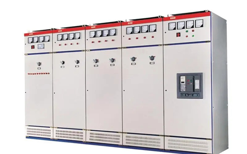

Definition of it

It is a three-phase power distribution product designed to safely, efficiently and reliably supply electric power at voltages up to 1,000 volts and current up to 6,000 amps.


Product introduction

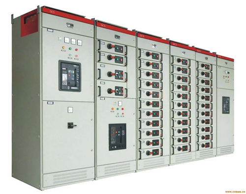
Low voltage switchgear is suitable for power plants, petroleum, chemical, metallurgy, textile, high-rise buildings and other industries, as well as for power transmission, distribution and energy conversion. The product complies with the standard of low voltage switchgear. Low voltage switchgear belongs to the products listed in the catalogue of compulsory certification products for 3C certification.


Main model

1. GCS low-voltage draw out switch cabinet
2. GCS low voltage switchgear
3. GCK with drawable switch cabinet
4. GGD low voltage fixed switch cabinet
5. Assembled low-voltage switchgear
6. MNS low-voltage draw out switch cabinet
7. MS low voltage draw out switch cabinet
8. GCS low-voltage draw out switch cabinet
9. Mnsqh with drawable low voltage switchgear
10. GCS low voltage draw out switch cabinet GCK (L) low voltage switch cabinet


Basic parameters

1. Rated insulation voltage: 690V
2. Rated working voltage: 380V, 660V
3. Rated frequency: 50Hz
4. Rated working current:
Rated current of horizontal bus: 630-6300a
Rated current of vertical bus 630-1600a
5. Rated short-time withstand current
Rated peak withstand current (is) 30-80ka
Rated short-time withstand current (is) 30-80ka
6. Rated withstand peak current
Horizontal bus (main bus) 63-176ka
Vertical bus (branch bus) 63-176ka


Usage condition

1. The ambient air temperature shall not exceed + 40 ℃ and not be lower than - 5 ℃, and the average temperature within 24h shall not exceed + 35 ℃.
2. The air shall be clean. When the maximum temperature is + 40 ℃, the relative humidity shall not exceed 50%. When the temperature is lower, a larger relative humidity is allowed.
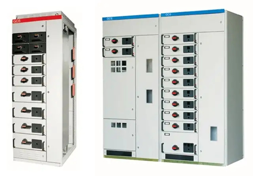
Drawer type low voltage switchgear
3. Pollution level: Level 3.
4. The elevation of the installation site shall not exceed 2000m.
5. Special use conditions shall be negotiated separately when ordering.


Performance characteristics
1. Reasonable design: carry out unit design according to the characteristics of various switches and combine the functional units;
2. General structure and flexible assembly: C-shaped profiles meet the requirements of various structural forms, i-protection grade and use surrounding conditions;
3. Standard module · it can be used to form protection, operation, conversion, control and other standard units, and the module structure can be arbitrarily selected;
4. Safety protection: adopt the isolation between regions and the mutual isolation between the incoming and outgoing lines of functional units to effectively strengthen the safety protection performance;
5. Technical parameters: the main technical parameters are at the international leading level.

WINSAFE NDI®HX3 Auto Tracking Live Steaming PTZ Camera release, it can be easy used on the training, education and church etc. live steaming situation, Which built-in auto-tracking function, don't need any third-party software or device, just turn on with one click on the WebUI, matching remote control or our control keyboard, and you can track the target accurately and smoothly without any outside interference. You can also switch the target accurately and smoothly without any outside interfrence. You can also switch the target talent, or set the target area, or change the target size. Easy setting, lower latency, better Image.


1080P Full HD 30X/20X, NDI®HX3, NDI®|HX3, 3G-SDI, HDMI and USB2.0 output image simultaneously as well. 3G-SDI and HDMI are for conventional video production workflow, and USB output can be used as a high-end webcam.


Welcome to ask more details and order sample for your testing. UHV-20X-IP-S(ATNDI)

AMC series USB3.0 PTZ Video Camera is equipped with a professional high quality 2 million pixel CMOS sensor and high-performance low-power SoC professional chip platform to continuously and stably output uncompressed 1080P high-definit.1/2.8" inch 2.14MP CMOS image sensor with resolution up to 1920 x 1080 at 60 frames per second, clearly displaying any image details, output smooth video without delay.


USB3.0 HDMI IP 20X IP PTZ Camera


12X/20X Optical zoom and 16X digital zoom to easily meet the requirements of close up and panorama views in various meeting scenes. Ultra Wide Angle, suitable for most steaming scenes, wide viewing angle with quality lens with high precision PTZ to meet your streaming needs. 64 Presets, close-up or panorama views can be switched at any time to improve the efficiency of the meeting.


One-Button Setting, Convenient and Efficient, Simple Design, Small and Light with HDM, LAN & USB 3.0 Interface. Good Design with cost effective, it is good used on the video conference, telemedicine, broadcating and education, if you have any interest, please feel free to contact with us.


AMC series USB3.0 PTZ Video Camera


WINSAFE AMC-G309UV2 4K Video Soundbar external cascade release. All-in-one Design, support External Casecase, 4K UHD camera with camera, microphone and speaker integrated, adopts advanced intelligent algorithm, accurate auto framing, speaker tracking.


4K Mini Video Soundbar


AMC-G309UV2 built-in high-sense mic array, pickup range up to 5 meters, supporting AGC, AEC, ANC, supporting 2 external cascade microphone to extend range up to 12M.


4K Mini Video Soundbar


110 degree UHD Lens/Supoer Wide HFOV,4KP30 UHD Video giving superb image, it is good used on the middle meeting room, not need other more euqipment, connect easy and let meeting will be more quick,clear and convenient.

Fan PCBA controllers and design services play a crucial role in ensuring efficient functioning of fans in various electronic devices. In this blog post, we will compare and contrast different products and services related to fan PCBA controllers, aiming to provide consumers with a comprehensive understanding. Whether you are looking for a fan PCB controller, digital fan controller, fan controller board, or auto heat and cool electric fan assembly, this article will help you make an informed decision.

Fan PCBA Controller

A fan PCBA controller is a device that regulates the speed and performance of a fan. It provides enhanced control and monitoring features, allowing users to adjust fan speeds and optimize cooling efficiency. Fan PCBA controllers come in various designs, from simple analog controllers to advanced digital controllers. These controllers are suitable for customizing fan speed and ensuring temperature management in computers, gaming consoles, and other electronic equipment.

Fan PCBA Design Service

On the other hand, fan PCBA design services focus on the development of customized fan PCBAs. These services offer professional assistance not only in PCB layout and design but also in selecting the right components for fan control devices. By utilizing a fan PCBA design service, you can ensure a precise fit for your specific applications and optimize performance.

Digital Fan Controller

A digital fan controller is a type of fan PCBA controller that utilizes digital signal processing technology. This controller enables precise control and offers advanced features like temperature sensing and automatic fan speed adjustment. Digital fan controllers are known for their accuracy and performance stability, making them ideal for applications that require strict temperature control while ensuring minimal noise.

Fan Controller Board

A fan controller board is a circuit board that integrates fan PCBA controllers and other associated circuits. It serves as a centralized hub for controlling multiple fans simultaneously. Fan controller boards offer convenience and flexibility, allowing users to manage several fans with ease. They are commonly used in high-performance gaming PCs, servers, and cooling systems.

Auto Heat and Cool Electric Fan Assembly

An auto heat and cool electric fan assembly is a complete system that includes a fan, PCBA controller, and sensors. This assembly is designed to automatically adjust fan speed based on the surrounding temperature. These systems offer energy efficiency and optimal cooling performance by dynamically responding to temperature changes.

In conclusion, when it comes to fan PCBA controllers and design services, understanding your specific requirements is crucial. If you require precise control and advanced features, digital fan controllers or fan controller boards can be your best option. On the other hand, if customization and tailored design are your priorities, opting for a professional fan PCBA design service can ensure optimal performance. Regardless of your needs, exploring all available options and considering the desired functionality will help you select the perfect fan PCBA solution for your applications.