In the world of modern technology, microwaves have become an indispensable part of our daily lives. From warming up our leftovers to cooking quick and delicious meals, microwaves provide convenience and ease in the kitchen. But have you ever wondered what makes these appliances work efficiently and safely? Enter microwave PCB boards, also known as microwave control boards or microwave printed circuit boards.

Understanding Microwave PCB Boards

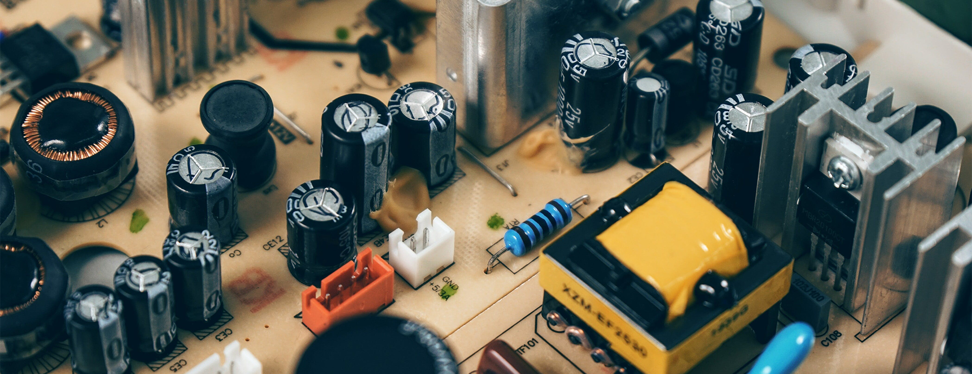
A microwave PCB board is a crucial component within a microwave that helps control its functions and ensures optimal performance. It is a specialized circuit board designed specifically for microwaves, facilitating the smooth operation of various features such as heating levels, timers, and sensors. These boards are carefully engineered to withstand the high frequencies and power associated with microwaves, making them an integral part of the appliance.

Key Functions of Microwave PCB Boards

One of the primary functions of microwave PCB boards is to regulate the flow of power to different components within the microwave. It acts as the brain of the appliance, controlling the overall operation and coordinating the communication between various parts. These boards also enable the microwave to maintain precise temperature and power levels, ensuring even cooking results.

Ensuring Safety and Efficiency

Microwave PCB boards play a critical role in ensuring the safety of both the appliance and the users. They incorporate safety mechanisms such as fuses and sensors to detect any faults or anomalies in the system. By monitoring and controlling the power distribution, these boards prevent overheating and protect against electrical failures.

Apart from safety, microwave PCB boards also contribute to the efficiency of the appliance. They are designed to minimize power wastage and optimize energy consumption. By seamlessly managing power output and distribution, these boards reduce operating costs and enhance the overall performance of the microwave.

Importance of Quality and Reliability

When it comes to microwave PCB boards, quality and reliability are paramount. Choosing a high-quality board ensures that the appliance functions optimally and lasts longer, providing a consistent and reliable cooking experience. Inferior or faulty boards can lead to inefficient heating, unreliable timers, or even pose safety hazards.

Microwave PCB boards are meticulously manufactured using advanced processes to meet industry standards and comply with safety regulations. It is essential to source these boards from reputable manufacturers who prioritize quality and adhere to rigorous testing methodologies. This ensures that the microwave operates reliably, guaranteeing precise control and longevity.

Conclusion

Next time you heat up a quick meal in your microwave, remember the micro-sized marvel that makes it all possible – the microwave PCB board. From providing control and safety to optimizing energy consumption, these tiny boards are the unsung heroes behind the scenes. By understanding their importance and choosing quality components, you can ensure that your microwave continues to serve you efficiently and reliably for years to come.
Small pixel pitch led screen is an emerging display technology with many advantages that make it attract attention in the field of TVs, monitors and other display devices. When it comes to micro-pitch displays, most people are unfamiliar with them. What are the main differences between them and ordinary displays? Today’s article will lead you to better break down this topic.


First of all, the technical principle of micro-pitch display is to use tiny LED elements to compose images. Each LED element is an independent light source, allowing precise brightness and color control. This is different from traditional LCD displays and organic light-emitting diode (OLED) displays, which have certain limitations on backlighting and luminescent materials. Micro-pitch displays use tiny self-illuminating LEDs to achieve higher brightness, higher contrast, and a wider color range, providing a better visual experience.


Secondly, micro-pitch displays have higher resolution and finer pixel pitch. Due to the tiny size of the LED elements, micro-pitch displays can achieve ultra-high definition resolution, making images clearer and more detailed. At the same time, the smaller pixel pitch also means that viewers can be closer when watching the big screen without feeling pixel graininess, providing a more realistic look and feel.


In addition, micro pixel pitch display offer excellent flexibility and customizability. The independence of LED elements allows micro-pitch displays to be customized as needed, enabling screens of various shapes and sizes. This makes micro-pitch displays have broad application prospects in large-scale events, commercial displays and customized applications.


On the other hand, ordinary display screens mainly include LCD displays and OLED displays. LCD displays use liquid crystal materials to control the transmission and blocking of light, while OLED displays use organic materials to emit light. Compared with micro-pitch displays, these traditional displays have some limitations in terms of brightness, contrast, and viewing angles. For example, the backlight system of an LCD display may result in a lower contrast ratio, while an OLED display may suffer from screen aging after prolonged use.


Micro-pitch display screens have attracted great attention in the field of display technology with their unique technical advantages and display effects. Although the cost may be higher, with the continuous advancement of technology and the advancement of large-scale production, micro-pitch displays are expected to gradually become the mainstream technology for large-screen display devices in the future.

Are you a kitchen hood control board enthusiast looking to upgrade your CEM-1 Cooker Hood LED Lighting PCB Board? Look no further! In this article, we will provide you with some valuable tips and tricks to help you enhance your cooking experience in style. Whether you’re a seasoned DIYer or new to the world of PCB boards, these suggestions will help you get the most out of your cooker hood LED lighting system.

1. Choose the Right LED Lights

When it comes to upgrading your cooker hood LED lighting, selecting the right LED lights is crucial. Look for energy-efficient LEDs with a high lumen output for bright and vibrant lighting. Consider warm white LEDs for a cozy ambience, or cool white LEDs for a modern and sleek look. Also, pay attention to the beam angle to ensure optimal light distribution.

2. Optimize Placement

Proper placement of LED lights on your cooker hood PCB board is essential. Install them strategically to ensure even illumination over your cooking area. Place them closer to the front edge of the hood to eliminate shadows caused by pots and pans. Experiment with different positions before securing the lights for an ideal setup.

3. Implement Dimming Functionality

Adding dimming functionality to your PCB board is a great way to control the intensity of your LED lighting. Install a dimmer switch or integrate a programmable microcontroller to achieve different lighting levels. Dimming your lights not only allows you to create the desired ambiance but also saves energy when full brightness is unnecessary.

4. Consider Color Changing LEDs

If you want to take your cooker hood LED lighting to the next level, consider using color-changing LEDs. These lights allow you to switch between various colors or even create dynamic lighting effects. With the right control mechanisms, you can easily transform your kitchen into a vibrant and visually appealing space.

5. Ensure Proper Heat Dissipation

Heat dissipation is crucial for the longevity of your PCB board. Make sure there is sufficient airflow around the LEDs and other components to prevent overheating. Consider adding heatsinks or fans to keep the temperature within safe limits. Regularly clean the hood to remove dust and debris that may obstruct airflow.

6. Maintain Proper Electrical Connections

To ensure the smooth operation of your LED lighting PCB board, it is essential to maintain proper electrical connections. Regularly check the solder joints and wiring to ensure they are secure and intact. Loose connections can lead to flickering lights or even complete failure. Periodically inspect and repair any damaged components to keep your board in optimal condition.

7. Follow Safety Guidelines

Lastly, always prioritize safety when working with electrical components. Before making any modifications or repairs, ensure that the power supply is disconnected to avoid any accidents. Familiarize yourself with safety procedures and guidelines to prevent electrical shocks or other hazards. If you’re unsure, consult a professional electrician.

By implementing these tips and tricks, you can enhance your CEM-1 Cooker Hood LED Lighting PCB Board and create a visually stunning and functional kitchen. Remember, upgrading your PCB board not only improves the aesthetics but also enhances the overall cooking experience. So, roll up your sleeves, get creative, and enjoy your beautifully illuminated kitchen!

If you’re an air conditioner control board enthusiast, then you know how important it is to have a reliable and efficient electronic board for your car’s air conditioning system. The SMT 7-segment car air conditioning electronic board is the backbone of your AC unit, responsible for controlling temperature, fan speed, and other essential functions. In this blog post, we will share some valuable tips and tricks to help you optimize the performance of your SMT 7-segment car air conditioning electronic board.

  1. Understand the Specifications: Before diving into any project, it’s crucial to carefully review the specifications of your SMT 7-segment car air conditioning electronic board. Familiarize yourself with its voltage requirements, pin configurations, and communication protocols. This understanding will help you determine compatibility with your car’s AC system and avoid any potential issues during installation.

  2. Proper Handling and Storage: SMT electronic boards are delicate and sensitive to electrostatic discharge (ESD). Always handle them with caution and wear an anti-static wristband to prevent damage. Additionally, store your electronic board in a dry and dust-free environment, away from direct sunlight and extreme temperatures.

  3. Soldering Techniques: When working with your SMT electronic board, it’s crucial to use proper soldering techniques to ensure reliable connections. Use a fine-tip soldering iron and high-quality solder wire. Practice good soldering habits, such as avoiding excessive heat, using flux, and inspecting solder joints for proper connection.

  4. Testing and Troubleshooting: Before installing your SMT 7-segment car air conditioning electronic board, it’s wise to test it thoroughly. Use a digital multimeter to check for continuity, resistance, and voltages. If any issues arise, troubleshoot by inspecting the board for loose connections, damaged components, or incorrect wiring.

  5. Software Configuration: Many SMT 7-segment car air conditioning electronic boards come with configurable software. Take advantage of this feature to customize temperature settings, fan speed levels, and other parameters according to your preferences. Refer to the user manual provided by the manufacturer for guidance on software configuration.

  6. Proper Ventilation: To ensure optimal performance and longevity of your electronic board, make sure it is installed in a well-ventilated area. High temperatures can adversely affect the board’s performance and reliability. Avoid placing it near heat sources like engine compartments or exhaust pipes.

  7. Regular Maintenance: Like any electronic component, your SMT 7-segment car air conditioning electronic board requires regular maintenance. Clean the board periodically using compressed air or a soft brush to remove dust and debris. Inspect for any signs of wear and tear, loose connections, or damaged components.

By following these tips and tricks, you can maximize the efficiency and durability of your SMT 7-segment car air conditioning electronic board. Remember to always refer to the manufacturer’s guidelines and seek professional assistance if needed. Happy tinkering and enjoy the cool breeze inside your car!

Disclaimer: Always exercise caution and follow appropriate safety measures when working with electronic components.

In the world of air conditioners, the electronic control board plays a vital role in ensuring efficient cooling and temperature regulation. With advancements in technology, several types of control boards have emerged, each with its own features and benefits. In this article, we will compare and contrast four popular options: the air conditioner electronic control board, the air conditioner universal control board, the PCBA for electronic products, and the automotive PCBA.

1. Air Conditioner Electronic Control Board

The air conditioner electronic control board is specifically designed for air conditioning units. It is engineered to monitor and control various functions such as temperature, fan speed, and mode settings. This dedicated control board offers precise performance and compatibility with specific air conditioner models. However, it may have limited functionality when compared to more versatile options.

2. Air Conditioner Universal Control Board

The air conditioner universal control board is a versatile solution that can work with a wide range of air conditioning units. This board is designed to be compatible with multiple brands and models, making it an ideal choice for users who have different air conditioners in their homes or offices. With additional options and programmable settings, this control board offers flexibility but may be slightly more complex to install and configure.

3. PCBA for Electronic Products

PCBA stands for Printed Circuit Board Assembly. This type of control board is not specifically designed for air conditioners but aims to serve various electronic products. While it may require customization to fit an air conditioning unit, it offers greater flexibility as it can be used across different electronic devices. The PCBA is a good option for those looking to integrate multiple functionalities into one control board.

4. Automotive PCBA

As the name suggests, the automotive PCBA is tailored for air conditioning systems in automobiles. This control board ensures efficient cooling and temperature control in vehicles. It may include additional features such as battery power optimization, compatibility with car sensors, and integrated diagnostics. While not suitable for regular home or office air conditioners, the automotive PCBA is an excellent choice for automotive air conditioning systems.

In conclusion, when selecting an electronic control board for your air conditioner, it is crucial to consider your specific requirements. The air conditioner electronic control board offers dedicated performance, the universal control board provides compatibility across multiple brands, the PCBA for electronic products allows versatility, while the automotive PCBA caters to vehicle air conditioning needs. Assessing your needs and understanding the capabilities of each option will help you make an informed decision based on your preferences and budget.

Wellav hospitality TV solution facilitates the reception of TV signals from diverse sourcesterrestrial, satellite, IP, or cable, as well as your own internal channelsand makes them available over your organization’s LAN, wireless network, WAN, internet, and mobile devices. Once on the network, the channels can be displayed on 500, 2000, or even more end-points.


This solution is easy to set up and can be expanded to include new services, features, and networks. You can set up 60 TV channels and 300 viewers starting from a few thousand dollars. The solution is ideal for the hospitality industry and can be implemented in government and educational institutions, horse racetracks, cruise lines, hospitals, casinos, and some private cable sectors.


An LC bandpass filter is an electronic circuit or device used in electronics and telecommunications to allow a specific range of frequencies to pass through while attenuating or blocking frequencies outside of that range. It is called an "LC" filter because it typically consists of passive components: inductors (L) and capacitors (C).

The LC bandpass filter is designed to have a certain center frequency (the frequency at which it provides maximum transmission) and a specified bandwidth (the range of frequencies it allows to pass through). It achieves this by using a combination of inductors and capacitors that create resonance at the center frequency, allowing signals around that frequency to pass with minimal attenuation.

LC bandpass filters are commonly used in various applications, including radio receivers, RF (radio frequency) communication systems, audio equipment, and more, where the selective filtering of a specific range of frequencies is essential for proper signal processing and rejection of unwanted signals or interference. They are a fundamental component in many electronic circuits and systems to ensure the desired signal quality and performance.

FiberTop launches the innovative 400G CFP2-DCO DWDM digital coherent optical module, providing a new solution for optical communication networks. This article describes the features and benefits of this new product.


The 400G CFP2-DCO coherent optical module uses a 104-pin CFP2-MSA electrical connector for connecting the host card. The module has following system performance and features:


  • Operating rate up to 425 Gbps
  • PM-QPSK (200G) and PM-16QAM (200G / 400G) and PM-16QAM PS (200G) modulation formats
  • 100GE, 200GE, 400GE and OTU4 / OTUCn services 
  • OTL4.4, FOIC1.4, CAUI-4 and FOIC1.2 electrical interfaces
  • Near-end / remote-end data loopback
  • CFP2 MSA Hardware Specification 1.0 with modifications compliant
  • CFP MSA Management Interface Specification 2.2 with modifications compliant
  • OTN framer and Ethernet MAC/PCS
  • LLDP packet listening
  • Hot-pluggable CFP2 form factor


The optical module consists of three functional parts: TX module, RX module and control module. All the control interface pins are provided by an internal microcontroller. This microcontroller can also be used for modulator control, software management, and alarm / performance event reporting.


The transmitter of the 400G CFP2-DCO coherent optical module provides a monitoring clock TXMCLK, which is mainly used as a reference for monitoring optical signals at the transmitter. This clock can be used to trigger a high-speed sampling oscilloscope.


FiberTop's 400G CFP2-DCO DWDM digital coherent optical module provides excellent transmission capabilities. It supports DWDM (Dense Wavelength Division Multiplexing) technology, capable of transmitting multiple signals of different wavelengths simultaneously on a single optical fiber. In high-density data centers or transmission networks, high-bandwidth transmission can be achieved, greatly improving the scalability and capacity of the network.


 Secondly, the module is highly adaptable and flexible. It is capable of transmission within a range of 120 kilometers to 1200 kilometers. With more choices and customized configurations, it is suitable for different network topologies and distance requirements.


For more information about Fibertop's 400G CFP2-DC DWDM digital coherent optical module, please contact us.

Microwave technology has revolutionized the world of electronics, enabling the development of powerful communication systems, sophisticated radar equipment, and high-frequency devices. One key component that plays a crucial role in these applications is the Microwave Printed Circuit Board (PCB). In this guide, we will walk you through the step-by-step process of using a Microwave PCB with electronic parts in the global market. Whether you are a beginner or someone looking to expand your knowledge, this guide will provide you with valuable insights.

Step 1: Understanding Microwave PCBs

Microwave PCBs are specifically designed to handle high-frequency signals and provide exceptional performance in microwave applications. Unlike regular PCBs, these boards are constructed using specialized materials like ceramic, Teflon, or fiberglass reinforced with PTFE. Before diving into the global market, it’s essential to gain a solid understanding of the unique characteristics and requirements of Microwave PCBs.

Step 2: Choose the Right Components

Selecting the appropriate electronic components is crucial for the successful integration of a Microwave PCB. Consider factors such as frequency range, power handling capacity, and temperature stability. Research various manufacturers and suppliers to ensure you get high-quality components that meet the specific requirements of your project.

Step 3: Design the Microwave PCB

Designing a Microwave PCB involves creating a layout that optimizes signal integrity and minimizes signal losses. It is recommended to use specialized PCB design software that provides advanced tools for high-frequency layouts. Ensure proper trace width, impedance matching, and careful placement of components to avoid signal reflections and interference.

Step 4: Prototype and Testing

Before mass production, it is essential to prototype and thoroughly test your design. Build a sample Microwave PCB and assemble the electronic parts according to your layout. Perform rigorous testing, including signal integrity analysis, power handling capacity, and thermal testing. Identify any issues and iterate on your design as needed.

Step 5: Compliance with Global Standards

To enter the global market, your Microwave PCB design and electronic parts must comply with various international standards and regulations. Research the specific standards required for your target markets, such as FCC for the United States or CE for Europe. Ensure your design meets these standards to guarantee the safety and performance of your product.

Step 6: Mass Production and Assembly

Once your design is thoroughly tested and compliant with global standards, you can proceed to mass production. Work with a reliable manufacturer who specializes in Microwave PCBs and electronic assembly. Provide them with detailed documentation and specifications to ensure the proper assembly of your PCBs with electronic parts.

Step 7: Quality Control and Packaging

Implement rigorous quality control measures to maintain consistent quality throughout the production process. Perform visual inspections, functional testing, and reliability testing to ensure your products meet or exceed customer expectations. Additionally, invest time in designing attractive and informative packaging that showcases your product’s features and benefits.

Step 8: Market Entry and Promotion

With your Microwave PCBs and electronic parts ready, it’s time to enter the global market. Develop a comprehensive marketing strategy to reach your target audience effectively. Leverage online platforms, social media, and industry-specific publications to promote your product. Participate in trade shows and exhibitions to showcase your offerings directly to potential customers.

Step 9: Customer Support and Feedback

Providing exceptional customer support is crucial for building a strong reputation in the global market. Establish channels for customer inquiries, technical assistance, and warranty support. Encourage customers to provide feedback and use constructive criticism to continuously improve your product and customer experience.

Step 10: Continuous Learning and Growth

The field of microwave technology is ever-evolving, with new advancements happening regularly. Stay updated with the latest industry trends, technological developments, and customer demands. Dedicate time and resources to continuous learning and research to ensure your Microwave PCBs and electronic parts remain competitive in the fast-paced global market.

By following these steps, you’ll be well on your way to successfully using Microwave PCBs with electronic parts in the global market. Remember, attention to detail, thorough testing, and dedication to meeting customer requirements are the keys to success. Embrace innovation and stay ahead of the curve, and your products will find a place in the global market.


Snap Frame Light Boxes vs. SEG Fabric Light Boxes


When it comes to illuminating graphics and displays, there are two popular options - SEG Fabric Light Boxes and Snap Frame Light Boxes. But which lighted frame is the better choice for your business?


SEG Fabric Light Boxes offer a sleek and modern design, with a tension fabric graphic that is stretched over a frame, creating a seamless and wrinkle-free look. The graphics are easy to change and can be customized to fit any size or shape. Plus, the LED lights provide bright and even illumination for an eye-catching display.


1.Vibrant colors - SEG fabric graphics are printed with dye sublimation, which produces vibrant and eye-catching colors.


2. Seamless and wrinkle-free - The silicone edge creates a tight, seamless appearance, and the fabric is stretched over the frame, ensuring there are no wrinkles or creases.


3. Easy to change graphics - The fabric graphic can be easily removed and replaced allowing for easy customization and updates.


4. Bright and even lighting - SEG fabric light boxes use LED lighting, which provides bright and even illumination across the entire graphic.


Snap frame led light box feature a snap-in graphic system that allows for easy graphic changes, but can sometimes result in a wrinkled appearance. The aluminum frames are durable, but can create a larger overall footprint compared to SEG Fabric Light Boxes. However, led poster light box may be more economical for smaller displays.


Snap frame light boxes share some benefits with their SEG fabric counterparts, such as customizable framing systems and easy access when transitioning between graphics. However, they also provide the following other advantages:

1.Easy to install - Snap frame light boxes are easy to install and can be mounted on walls or ceilings.


2. Cost-effective - Snap frame light boxes are a cost-effective option compared to other light boxes.


3. Durable - Snap frame light boxes are made of durable aluminum frames, which can withstand wear and tear.


4. Aesthetically pleasing - The backlit photo frame provide a clean, slimline appearance and allow for easy graphic changes.


5. Graphic Protection - We use a piece of transparent acrylic or polycarbonate that is inserted within the led snap frame, on top of the backlit film to protect it. It helps prevent weather damage or vandalism, to ensure that the content is protected. Snap frames light boxes can be used indoor or outdoor, and will be weather proofed.


Ultimately, the decision between fabric light box frame and Snap Frame Light Boxes depends on your specific needs and budget. Consider the size of your display, frequency of graphic changes, and desired aesthetic when making your choice. Either way, both options will provide a professional and illuminated display for your business.


If you need a light box to augment print advertising at your company, turn to luzleddisplays for solutions. Our made-to-order light boxes come in backlit and edge lit styles, which feature heavy-duty yet lightweight aluminum frames and long-lasting, energy-efficient LED lights. Clients may also request custom designs tailored to their distinct signage needs. Contact us today to learn more about the benefits of light boxes and our products.


LED Snap Frame LED Snap Frame Fabric Light Box Frame Fabric Light Box Frame